ATmega48/88/168
Writing this bit to one enables the USART Receiver in MSPIM mode. The Receiver will override
normal port operation for the RxDn pin when enabled. Disabling the Receiver will flush the
receive buffer. Only enabling the receiver in MSPI mode (i.e. setting RXENn=1 and TXENn=0)
has no meaning since it is the transmitter that controls the transfer clock and since only master
mode is supported.
• Bit 3 - TXENn: Transmitter Enable
Writing this bit to one enables the USART Transmitter. The Transmitter will override normal port
operation for the TxDn pin when enabled. The disabling of the Transmitter (writing TXENn to
zero) will not become effective until ongoing and pending transmissions are completed, i.e.,
when the Transmit Shift Register and Transmit Buffer Register do not contain data to be trans-
mitted. When disabled, the Transmitter will no longer override the TxDn port.
• Bit 2:0 - Reserved Bits in MSPI mode
When in MSPI mode, these bits are reserved for future use. For compatibility with future devices,
these bits must be written to zero when UCSRnB is written.
18.6.4
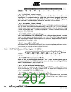
USART MSPIM Control and Status Register n C - UCSRnC
Bit
7
6
5
4
3
-
2
UDORDn
R/W
1
UCPHAn
R/W
0
UCPOLn
R/W
UMSELn1
UMSELn0
-
-
UCSRnC
Read/Write
Initial Value
R/W
0
R/W
0
R
0
R
0
R
0
1
1
0
• Bit 7:6 - UMSELn1:0: USART Mode Select
These bits select the mode of operation of the USART as shown in Table 18-3. See ”USART
Control and Status Register n C – UCSRnC” on page 189 for full description of the normal
USART operation. The MSPIM is enabled when both UMSELn bits are set to one. The
UDORDn, UCPHAn, and UCPOLn can be set in the same write operation where the MSPIM is
enabled.
Table 18-3. UMSELn Bits Settings
UMSELn1
UMSELn0
Mode
0
0
1
1
0
1
0
1
Asynchronous USART
Synchronous USART
(Reserved)
Master SPI (MSPIM)
• Bit 5:3 - Reserved Bits in MSPI mode
When in MSPI mode, these bits are reserved for future use. For compatibility with future devices,
these bits must be written to zero when UCSRnC is written.
• Bit 2 - UDORDn: Data Order
When set to one the LSB of the data word is transmitted first. When set to zero the MSB of the
data word is transmitted first. Refer to the Frame Formats section page 4 for details.
• Bit 1 - UCPHAn: Clock Phase
The UCPHAn bit setting determine if data is sampled on the leasing edge (first) or tailing (last)
edge of XCKn. Refer to the SPI Data Modes and Timing section page 4 for details.
203
2545E–AVR–02/05

 MICROCHIP [ MICROCHIP ]