ML4901
DESIGN CONSIDERATIONS
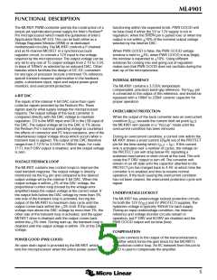
This section is a quick-check guide for getting ML4901
circuits up and running, with a special emphasis on
Pentium Pro applications. All component designators refer
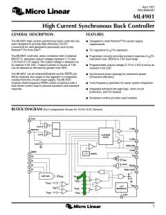
to the circuit shown in Figure 1.
ESL (66mV). To meet this requirement, the output ESR
should not exceed:
100mV
ESR(MAX) =
= 7.3mW
(2)
(3)
13.7A
COMPENSATION
With the effects of ESL limited to 2% of 3.3V, the
maximum ESL is:
The R and C values connected to the COMP pin for loop
compensation are 330kΩ and 33pF, respectively. These
values yield stable operation and rapid transient response
1ms
ESL(MAX) =
´ 66mV = 2.2nH
for a most values of L and C
(1µH to 5µH, 1200µF to
OUT
30A
10,000µF), and will generally not need to be altered. If
changes do need to be made, note that the drive capability
of the transconductance error amplifier is typically 10µA,
Achieving these low a values of ESL and ESR is not trivial;
doing so typically requires using several high-quality
capacitors in parallel. Dedicated power and ground planes
are helpful as well.
its Z
is 10 MΩ, and its unity-gain frequency is
OUT
approximately 10 MHz.
The output capacitance should have a value of > 2200µF
to hold the output voltage relatively constant (<50mV of
sag) until the current in the buck inductor can catch up
with the change in output current. To meet the ESR and
ESL requirements, the actual output capacitance will
usually be significantly greater than this theoretical
minimum. These capacitors can be of all one type, or a
combination of aluminum electrolytic, OS-CON, and
tantalum devices.
INPUT AND OUTPUT CAPACITORS
The input and output capacitors used in conjunction with
the ML4901, especially in Pentium Pro VRM applications,
must be able to meet several criteria:
1. The input capacitors must be able to handle a relatively
high ripple current
2. The output capacitors must have a low Equivalent Series
Resistance (ESR) and Equivalent Series Inductance (ESL)
OVERCURRENT PROTECTION
3. The output capacitors must be able to hold up the
output during the time that the current through the buck
inductor is slewing to meet a transient load step.
Current sense resistor R1 is used to monitor the inductor
current during the off period, i.e., while current is flowing
through the synchronous rectifier (or Schottky diode, if no
synchronous rectifier MOSFET is used). The internal
current sense comparator has been designed to provide in
excess of 14A of output current when used with a 6mΩ
resistor. R1 must be a low inductance part such as Dale/
Vishay’s type WSL-2512-.006±1%. This is a 6mΩ surface
mount part rated at 1 Watt. Using a PCB trace as a current
sense element is not recommended due to the high
temperature coefficient of copper, and due to etching and
plating tolerances which can occur from board to board.
The circuit’s input bypass capacitance should be able to
handle a ripple current equal to 0.5 x I
. If the
LOAD
converter sees load peaks only occasionally, and for less
than 30 seconds at a time during those intervals, then
®
aluminum electrolytic or OS-CON input capacitors need
only be sized to accommodate the average output load.
Note that tantalum input capacitors have much less
thermal mass than aluminum electrolytics, so this
relaxation of ripple current requirements may not apply to
them.
The R and C values connected to the PROTECT pin for
setting the current limit delay and the off-time of the
hiccup mode are 100kΩ and 1µF, respectively. These
values will protect most MOSFETs from overheating
during a short circuit condition. If it is necessary to change
the ratio of ON and OFF times during overcurrent
conditions, this can be done by selecting a different value
for C13. Larger values of C13 will increase the delay
between retry attempts (the length of the “hiccup”).
During a 30A/µs load transient, it is not practical for a
buck converter to slew its output current fast enough to
regulate the instantaneous output voltage required by this
application. During the first few microseconds following
such a load step, the output capacitance of the converter
must act as passive energy storage. In delivering its energy
to the load, the output capacitance must not introduce any
considerable impedance, or its purpose will be defeated. A
total voltage aberration during load transients of ±5% is
allowed (see Intel AP-523). The voltage transient due to
ESL and ESR is:
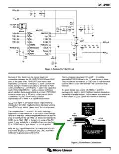
The voltage across current sense resistor R1 must be
Kelvin-sensed. This ensures that the ML4901 monitors only
the voltage across this resistor and not the voltage drops or
inductive transients in the PCB traces which carry current
into and out of this resistor. The two pins of the ML4901
which must be Kelvin-connected to the sense resistor are
∆V = L
di O
I
+ FESL ×
OUT g
G
ESR × ∆I
b
J
P
(1)
M
H
dtK
N
Q
I
and GND. There is no connection inside the
SENSE
For example, assume that a 3.3V output has 3% of the
output's ∆V contributed by ESR (100mV)and 2% by the
ML4901 between GND and PWR GND. This is to facilitate
the requisite Kelvin-sensing of the voltage across R1.
6

 MICRO-LINEAR [ MICRO LINEAR CORPORATION ]