Micrel
MIC4830
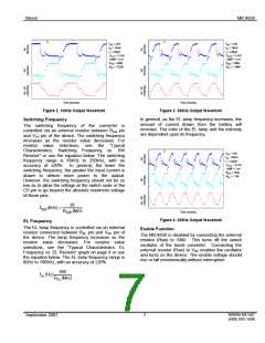
V
= 3.6V
V
= 3.6V
IN
= 12mA
IN
I = 19mA
I
IN
L = 220µH
= 2.7nF
IN
L = 220µH
= 2.7nF
C
C
OUT
LAMP = 2 in2
OUT
LAMP = 2 in2
R
R
= 250k
R
R
= 290k
SW
SW
= 2.82M
= 1.69M
EL
EL
Time (2ms/div)
Time (2ms/div)
Figure 2. 100Hz Output Waveform
Figure 3. 200Hz Output Waveform
Switching Frequency
In general, as the EL lamp frequency increases, the
amount of current drawn from the battery will
increase. The color of the EL lamp and the intensity
are dependent upon its frequency.
The switching frequency of the converter is
controlled via an external resistor between RSW pin
and VDD pin of the device. The switching frequency
increases as the resistor value decreases. For
resistor value selections, see the “Typical
Characteristics: Switching Frequency vs. SW
Resistor” or use the equation below. The switching
frequency range is 65kHz to 250kHz, with an
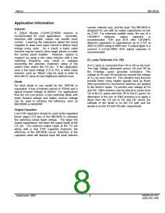
V
= 3.6V
IN
= 25mA
I
IN
L = 220µH
= 2.7nF
C
OUT
LAMP = 2 in2
accuracy of ±20%.
In general, the lower the
switching frequency, the greater the input current is
drawn to deliver more power to the output.
However, the switching frequency should not be so
low as to allow the voltage at the switch node or the
CS pin to go beyond the absolute maximum voltage
of those pins.
R
R
= 352k
= 1.1M
SW
EL
36
fSW (kHz) =
RSW
(
MΩ
)
Time (2ms/div)
Figure 4. 300Hz Output Waveform
EL Frequency
The EL lamp frequency is controlled via an external
resistor connected between REL pin and VDD pin of
the device. The lamp frequency increases as the
resistor value decreases. For resistor value
selections, see the “Typical Characteristics: EL
Frequency vs. EL Resistor” graph on page 4 or use
the equation below. The EL lamp frequency range is
60Hz to 1000Hz, with an accuracy of ±20%.
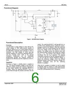
Enable Function
The MIC4830 is disabled by connecting the external
resistor (Rsw) to GND. This turns off the switch
oscillator of the boost converter. Connecting the
external resistor (Rsw) to VDD enables the oscillator
and turns on the device. The enable voltage should
rise or fall monotonically without interruption.
360
fEL
(
Hz
)
REL
(
MΩ
)
M9999-091307
(408) 955-1690
September 2007
7

 MICREL [ MICREL SEMICONDUCTOR ]