MIC39500/39501
Micrel
pared with the dropout voltage. Use a series input resistor
to drop excessive voltage and distribute the heat between
this resistor and the regulator. The low-dropout properties of
MicrelSuperβetaPNPregulatorsallowsignificantreductions
in regulator power dissipation and the associated heat sink
without compromising performance. When this technique
is employed, a capacitor of at least 1µF is needed directly
between the input and regulator ground.
Applications Information
The MIC39500/1 is a high-performance low-dropout voltage
regulatorsuitableformoderatetohigh-currentvoltageregula-
tor applications. Its 400mV dropout voltage at full load makes
it especially valuable in battery-powered systems and as a
high-efficiency noise filter in post-regulator applications. Un-
like older NPN-pass transistor designs, where the minimum
dropout voltage is limited by the base-to-emitter voltage drop
and collector-to-emitter saturation voltage, dropout perfor-
mance of the PNP output of these devices is limited only by
Refer to Application Note 9 for further details and examples
on thermal design and heat sink specification.
the low V saturation voltage.
Output capacitor
CE
Atrade-off for the low dropout voltage is a varying base drive
requirement.Micrel’sSuperβetaPNP™processreducesthis
drive requirement to only 2% to 5% of the load current.
The MIC39500/1 requires an output capacitor to maintain
stability and improve transient response. Proper capaci-
tor selection is important to ensure proper operation. The
MIC39500/1outputcapacitorselectionisdependentuponthe
ESR (equivalent series resistance) of the output capacitor to
maintainstability.Whentheoutputcapacitoris47µForgreater,
the output capacitor should have less than 1Ω of ESR. This
will improve transient response as well as promote stability.
Ultra-low-ESR capacitors, such as ceramic chip capacitors
may promote instability. These very low ESR levels may
causeanoscillationand/orunderdampedtransientresponse.
When larger capacitors are used, the ESR requirement ap-
proaches zero. A 100µF ceramic capacitor can be used on
the output while maintaining stability. A low-ESR 47µF solid
tantalum capacitor works extremely well and provides good
transient response and stability over temperature.Aluminum
electrolytics can also be used, as long as the ESR of the
capacitor is < 1Ω.
TheMIC39500/1regulatorisfullyprotectedfromdamagedue
to fault conditions. Current limiting is provided. This limiting is
linear; output current during overload conditions is constant.
Thermalshutdowndisablesthedevicewhenthedietempera-
tureexceedsthemaximumsafeoperatingtemperature.Tran-
sient protection allows device (and load) survival even when
theinputvoltagespikesaboveandbelownominal.Theoutput
structureoftheseregulatorsallowsvoltagesinexcessofthede-
siredoutputvoltagetobeappliedwithoutreversecurrentflow.
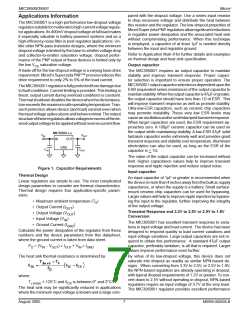
MIC39500-x.x
VIN
VOUT
IN
OUT
GND
CIN
COUT
The value of the output capacitor can be increased without
limit. Higher capacitance values help to improve transient
response and ripple rejection and reduce output noise.
Figure 1. Capacitor Requirements
Thermal Design
Input capacitor
An input capacitor of 1µF or greater is recommended when
thedeviceismorethan4inchesawayfromthebulkacsupply
capacitance, or when the supply is a battery. Small surface-
mount ceramic chip capacitors can be used for bypassing.
Larger values will help to improve ripple rejection by bypass-
ing the input to the regulator, further improving the integrity
of the output voltage.
Linear regulators are simple to use. The most complicated
design parameters to consider are thermal characteristics.
Thermal design requires four application-specific param-
eters:
• Maximum ambient temperature (T )
A
• Output Current (I
)
OUT
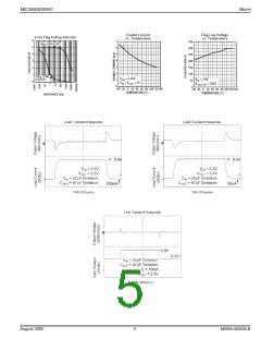
Transient Response and 3.3V to 2.5V or 2.5V to 1.8V
Conversion
• Output Voltage (V
)
)
OUT
• Input Voltage (V )
IN
The MIC39500/1 has excellent transient response to varia-
tions in input voltage and load current. The device has been
designed to respond quickly to load current variations and
input voltage variations. Large output capacitors are not re-
quired to obtain this performance. A standard 47µF output
capacitor, preferably tantalum, is all that is required. Larger
values improve performance even further.
• Ground Current (I
GND
Calculate the power dissipation of the regulator from these
numbers and the device parameters from this datasheet,
where the ground current is taken from data sheet.
P = (V – V
) × I
+ V × I
D
IN
OUT
OUT IN GND
The heat sink thermal resistance is determined by:
By virtue of its low-dropout voltage, this device does not
saturate into dropout as readily as similar NPN-based de-
signs. When converting from 3.3V to 2.5V, or 2.5V to 1.8V,
the NPN-based regulators are already operating in dropout,
with typical dropout requirements of 1.2V or greater. To con-
vert down to 2.5V without operating in dropout, NPN-based
regulators require an input voltage of 3.7V at the very least.
The MIC39500/1 regulator provides excellent performance
where:
T
≤ 125°C and θ is between 0° and 2°C/W.
CS
J (max)
The heat sink may be significantly reduced in applications
where the minimum input voltage is known and is large com-
August 2005
7
M9999-082605-B

 MICREL [ MICREL SEMICONDUCTOR ]