KSZ8795CLX
9.0
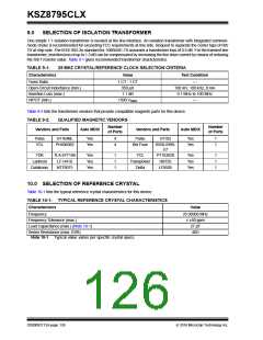
SELECTION OF ISOLATION TRANSFORMER
One simple 1:1 isolation transformer is needed at the line interface. An isolation transformer with integrated common-
mode choke is recommended for exceeding FCC requirements at line side. Request to separate the center taps of RX/
TX at chip side. The IEEE 802.3u standard for 100BASE-TX assumes a transformer loss of 0.5 dB. For the transmit line
transformer, insertion loss of up to 1.3 dB can be compensated by increasing the line drive current by means of reducing
the ISET resistor value. Table 9-1 gives recommended transformer characteristics.
TABLE 9-1:
25 MHZ CRYSTAL/REFERENCE CLOCK SELECTION CRITERIA
Characteristics
Value
Test Condition
Turns Ratio
1 CT : 1 CT
350 µH
—
Open-Circuit Inductance (min.)
Insertion Loss (max.)
HIPOT (min.)
100 mV, 100 kHz, 8 mA
0.1 MHz to 100 MHz
—
1.1 dB
1500 VRMS
Table 9-2 lists the transformer vendors that provide compatible magnetic parts for this device.
TABLE 9-2:
QUALIFIED MAGNETIC VENDORS
Number
Number
of Ports
Vendors and Parts
Auto MDIX
Vendors and Parts
Auto MDIX
of Ports
Pulse
YCL
H1164NL
Yes
Yes
4
4
Pulse
H1102
Yes
Yes
1
1
PH406082
Bel Fuse
S558-5999-
U7
TDK
TLA-6T718A
LF-H41S
Yes
Yes
Yes
1
1
1
YCL
Transpower
Delta
PT163020
HB726
Yes
Yes
Yes
1
1
1
LanKom
Datatronic
NT79075
LF8505
10.0 SELECTION OF REFERENCE CRYSTAL
Table 10-1 lists the typical reference crystal characteristics for this device.
TABLE 10-1: TYPICAL REFERENCE CRYSTAL CHARACTERISTICS
Characteristics
Value
Frequency
25.00000 MHz
≤ ±50 ppm
27 pF
Frequency Tolerance (max.)
Load Capacitance (max.) (Note 10-1)
Series Resistance (max. ESR)
40ꢀ
Note 10-1
Typical value varies per specific crystal specs.
DS00002112A-page 126
2016 Microchip Technology Inc.

 MICREL [ MICREL SEMICONDUCTOR ]