Micrel, Inc.
KSZ9021RL/RN
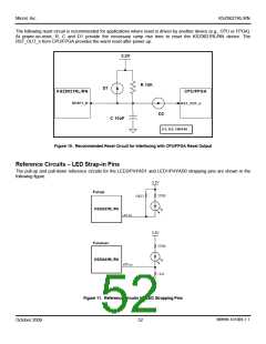
The following reset circuit is recommended for applications where reset is driven by another device (e.g., CPU or FPGA).
At power-on-reset, R, C and D1 provide the necessary ramp rise time to reset the KSZ9021RL/RN device. The
RST_OUT_n from CPU/FPGA provides the warm reset after power up.
3.3V
R 10K
D1
KSZ9021RL/RN
CPU/FPGA
RESET_N
RST_OUT_n
D2
C 10uF
D1, D2: 1N4148
Figure 10. Recommended Reset Circuit for Interfacing with CPU/FPGA Reset Output
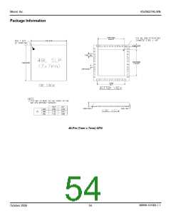
Reference Circuits – LED Strap-in Pins
The pull-up and pull-down reference circuits for the LED2/PHYAD1 and LED1/PHYAD0 strapping pins are shown in the
following figure.
Figure 11. Reference Circuits for LED Strapping Pins
M9999-101309-1.1
October 2009
52

 MICREL [ MICREL SEMICONDUCTOR ]