Micrel, Inc.
KSZ9021RL/RN
Pin Number
Pin Name
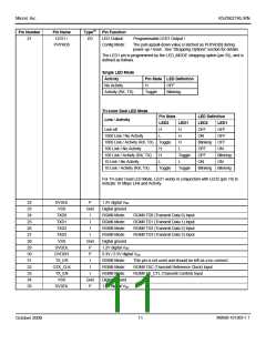
LED1 /
Type(1)
Pin Function
LED Output:
Config Mode:
21
I/O
Programmable LED1 Output /
PHYAD0
The pull-up/pull-down value is latched as PHYAD[0] during
power-up / reset. See “Strapping Options” section for details.
The LED1 pin is programmed by the LED_MODE strapping option (pin 55), and is
defined as follows.
Single LED Mode
Activity
Pin State LED Definition
No Activity
H
OFF
Activity (RX, TX)
Toggle
Blinking
Tri-color Dual LED Mode
Link / Activity
Pin State
LED Definition
LED2
LED1
LED2
OFF
LED1
Link off
H
L
H
OFF
1000 Link / No Activity
H
ON
OFF
1000 Link / Activity (RX, TX) Toggle
H
Blinking
OFF
OFF
100 Link / No Activity
H
L
ON
100 Link / Activity (RX, TX)
10 Link / No Activity
H
Toggle
L
OFF
Blinking
ON
L
ON
10 Link / Activity (RX, TX)
Toggle
Toggle
Blinking
Blinking
For Tri-color Dual LED Mode, LED1 works in conjunction with LED2 (pin 19) to
indicate 10 Mbps Link and Activity.
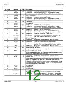
22
23
24
25
26
27
28
29
30
31
32
33
34
35
DVDDL
VSS
P
1.2V digital VDD
Digital ground
Gnd
TXD0
I
RGMII Mode:
RGMII Mode:
RGMII Mode:
RGMII Mode:
Digital ground
1.2V digital VDD
RGMII TD0 (Transmit Data 0) Input
RGMII TD1 (Transmit Data 1) Input
RGMII TD2 (Transmit Data 2) Input
RGMII TD3 (Transmit Data 3) Input
TXD1
I
TXD2
I
TXD3
I
VSS
Gnd
DVDDL
DVDDH
TX_ER
GTX_CLK
TX_EN
VSS
P
P
3.3V / 2.5V digital VDD
I
RGMII Mode:
RGMII Mode:
RGMII Mode:
Digital ground
1.2V digital VDD
This pin is not used and should be left as a no connect.
I
I
RGMII TXC (Transmit Reference Clock) Input
RGMII TX_CTL (Transmit Control) Input
Gnd
P
DVDDL
M9999-101309-1.1
October 2009
11

 MICREL [ MICREL SEMICONDUCTOR ]