C/T2: Timer or counter select. 0 is for timer and 1 is for external event counter.
CP/RL2: Capture/Reload flag. When set, captures will occurs on a negative transition at T2EX if EXEN2=1.
When cleared, auto-reloads will occur either with Timer2 overflows or a negative transition at
T2EX when EXEN2=1. When whether TCLK or RCLK is 1, this bit is ignored and the timer is
forced to auto-reload on Timer2 overflow.
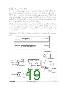
TIMER0 (T0) AND TIMER1 (T1)
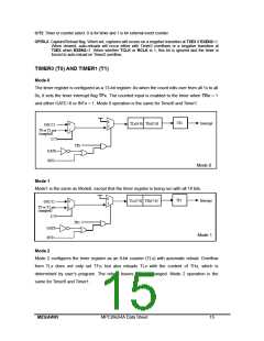
Mode 0
The timer register is configured as a 13-bit register. As when the count rolls over from all 1s to all
0s, it sets the timer interrupt flag TFx. The counted input is enabled to the timer when TRx = 1
and either GATE=0 or INTx = 1. Mode 0 operation is the same for Timer0 and Timer1.
0
1
TFx
Interrupt
TLx[4:0] THx[7:0]
0
1
OSC/12
T0 or T1 pin
(sampled)
TRx
GATE
/INTx
Mode 0
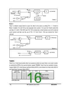
Mode 1
Mode1 is the same as Mode0, except that the timer register is being run with all 16 bits.
0
1
TFx
Interrupt
TLx[7:0] THx[7:0]
0
1
OSC/12
T0 or T1 pin
(sampled)
C//T
TRx
GATE
Mode 1
/INTx
Mode 2
Mode 2 configures the timer register as an 8-bit counter (TLx) with automatic reload. Overflow
from TLx does not only set TFx, but also reloads TLx with the content of THx, which is
determined by user’s program. The reload leaves THx unchanged. Mode 2 operation is the
same for Timer0 and Timer1.
MEGAWIN
MPC89x54A Data Sheet
15

 MEGAWIN [ MEGAWIN TECHNOLOGY CO., LTD ]