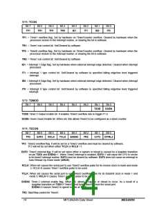
SFR: TCON
Bit-7
Bit-6
Bit-5
Bit-4
Bit-3
Bit-2
Bit-1
Bit-0
TF1
TR1
TF0
TR0
IE1
IT1
IE0
IT0
TF1: = Timer1 overflow flag. Set by hardware on Timer/Counter overflow. Cleared by hardware when the
processor vectors to the interrupt routine, or clearing the bit in software.
TR1: = Timer1 run control bit. Set/Cleared by software.
TF0: = Timer0 overflow flag. Set by hardware on Timer/Counter overflow. Cleared by hardware when the
processor vectors to the interrupt routine, or clearing the bit in software.
TR0: = Timer1 run control bit. Set/Cleared by software.
IE1: = Interrupt 1 Edge flag. Set by hardware when external interrupt edge detected. Cleared when interrupt
processed.
IT1: = Interrupt 1 type control bit. Set/Cleared by software to specified falling edge/low level triggered
interrupt.
IE0: = Interrupt 0 Edge flag. Set by hardware when external interrupt edge detected. Cleared when interrupt
processed.
IT0: = Interrupt 0 type control bit. Set/Cleared by software to specified falling edge/low level triggered
interrupt.
SFR: T2MOD
Bit-7
Bit-6
Bit-5
Bit-4
Bit-3
Bit-2
Bit-1
Bit-0
T2OE
DCEN
T2OE: Timer 2 Output Enable bit. It enables Timer2 overflow rate to toggle P1.0.
DCEN: Down Count Enable bit. When set, this allows Timer2 to be configured as a down counter.
SFR: T2CON
Bit-7
Bit-6
Bit-5
Bit-4
Bit-3
Bit-2
Bit-1
Bit-0
TF2
EXF2
RCLK
TCLK
EXEN2
TR2
C//T2
CP/RL2
TF2 : Timer2 overflow flag. It will be set by a Timer2 overflow and must be cleared by software.
TF2 will not be set when either TCLK or RCLK =1.
EXF2 :Timer2 external flag. It will be set when either a capture or reload is caused by a negative transition
on pin T2EX and EXEN2=1. When Timer2 interrupt is enabled, EXF2=1 will cause the CPU to vector
to he timer2 interrupt routine. EXF2 must be cleared by software. EXF2 does not cause an interrupt in
Auto-Reload Up-Down mode (ARUD).
RCLK: When set causes the serial port to use Timer2 overflow pulse for its receive clock in mode and mode
3. RCLK=0 causes Timer1 overflow pulse to be used.
TCLK: When set causes the serial port to use Timer2 overflow pulse for its transmit clock in mode 1 and
mode 3. RCLK=0 causes Timer1 overflow pulse to be used.
EXEN2: Timer-2 external enable flag. When set, allows a capture or reload to occur. As a result of a
negative transition on T2EX if Timer2 is not being used to clock the serial port.
EXEN2=0 causes Timer2 to ignore events at T2EX.
TR2: Start/Stop control for Timer2.
14
MPC89x54A Data Sheet
MEGAWIN

 MEGAWIN [ MEGAWIN TECHNOLOGY CO., LTD ]