never clears the interrupt flags of Timer2, Serial Port, PCA, Brownout Detection and UART2. This has to be done
in the user’s software. It clears an external interrupt flag (IE0, IE1, IE2 or IE3) only if it was transition-activated.
The hardware-generated LCALL pushes the contents of the Program Counter onto the stack (but it does not save
the PSW) and reloads the PC with an Vector Address that depends on the source of the interrupt being vectored
to, as shown in Table 19-1.
Execution proceeds from that location until the RETI instruction is encountered. The RETI instruction informs the
processor that this interrupt routine is no longer in progress, then pops the top two bytes from the stack and
reloads the Program Counter. Execution of the interrupted program continues from where it left off.
Note that a simple RET instruction would also have returned execution to the interrupted program, but it would
have left the interrupt control system thinking the interrupt was still in progress.
Note that the starting addresses of consecutive interrupt service routines are only 8 bytes apart. That means if
consecutive interrupts are being used (IE0 and TF0, for example, or TF0 and IE1), and if the first interrupt routine
is more than 7 bytes long, then that routine will have to execute a jump to some other memory location where the
service routine can be completed without overlapping the starting address of the next interrupt routine
19.6 External Interrupts
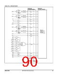
The external sources includes /INT0, /INT1, /INT2 and /INT3, which can each be either level-activated (low-level)
or transition-activated (falling-edge), depending on bits IT0, IT1, IT2 and IT3 in registers TCON and XICON. If ITx
= 0, external interrupt x is triggered by a detected low at the INTx pin. If ITx = 1, external interrupt x is negative
edge-triggered. The flags that actually generate these interrupts are bits IE0 and IE1 in TCON and IE2 and IE3 in
XICON. These flags are cleared by hardware when the service routine is vectored to only if the interrupt was
transition-activated. If the interrupt was level-activated, then the external requesting source is what controls the
request flag, rather than the on-chip hardware.
Since the external interrupt pins are sampled once each instruction cycle, an input high or low should hold for at
least one oscillator period to ensure sampling. If the external interrupt is transition-activated, the external source
has to hold the request pin high for at least one cycle, and then hold it low for at least one cycle to ensure that the
transition is seen so that interrupt request flag IEx will be set. IEx will be automatically cleared by the CPU when
the service routine is called.
If external interrupt is level-activated, the external source has to hold the request active until the requested
interrupt is actually generated. Then it has to deactivate the request before the interrupt service routine is
completed, or else another interrupt will be generated right again.
19.7 Single-Step Operation
The 80C51 interrupt structure allows single-step execution with very little software overhead. As previously noted,
an interrupt request will not be responded to while an interrupt of equal or higher priority level is still in progress,
nor will it be responded to after RETI until at least one other instruction has been executed. Thus, once an
interrupt routine has been entered, it cannot be re-entered until at least one instruction of the interrupted program
is executed. One way to use this feature for single-step operation is to program one of the external interrupts
(e.g., INT0) to be level-activated. The service routine for the interrupt will terminate with the following code:
JNB P3.2,$ ;Wait Till INT0 Goes High
JB
RETI
P3.2,$ ;Wait Till INT0 Goes Low
;Go Back and Execute One Instruction
Now if the INT0 pin, which is also the P3.2 pin, is held normally low, the CPU will go right into the External
Interrupt 0 routine and stay there until INT0 is pulsed (from low to high to low). Then it will execute RETI, go back
to the task program, execute one instruction, and immediately re-enter the External Interrupt 0 routine to await
the next pulsing of P3.2. One step of the task program is executed each time P3.2 is pulsed.
MEGAWIN
MPC82G516A Data Sheet
94

 MEGAWIN [ MEGAWIN TECHNOLOGY CO., LTD ]