Prior to using the ADC function, the user should:
1) Turn on the ADC hardware by setting the ADCON bit,
2) Configure the conversion speed by bits SPEED1 and SPEED0,
3) Select the analog input channel by bits CHS1 and CHS0,
4) Configure the selected input (shared with P1) to the Input-Only mode by P1M0 and P1M1 registers, and
5) Configure ADC result arrangement using ADRJ bit.
Now, user can set the ADCS bit to start the A-to-D conversion. The conversion time is controlled by bits SPEED1
and SPEED0. Once the conversion is completed, the hardware will automatically clear the ADCS bit, set the
interrupt flag ADCI and load the 10 bits of conversion result into ADCH and ADCL (according to ADRJ bit)
simultaneously.
As described above, the interrupt flag ADCI, when set by hardware, shows a completed conversion. Thus two
ways may be used to check if the conversion is completed: (1) Always polling the interrupt flag ADCI by software;
(2) Enable the ADC interrupt by setting bits EADC (in AUXIE register) and EA (in IE register), and then the CPU
will jump into its Interrupt Service Routine when the conversion is completed. Regardless of (1) or (2), the ADCI
flag should be cleared by software before next conversion.
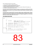
16.3 Sample Code for ADC
start:
;...
;...
MOV
ADCTL,#0E2h
;ADCON=1, turn on ADC hardware
;(SPEED1,SPEED0)=(1,1), Conv. Time= 270 clock cycles
;select AIN0 (P1.2) as analog input
ORL
ANL
P1M0,#00000100B ;P1M0,bit2=1 ;configure P1.2 as Input-Only Mode
P1M1,#11111011B ;P1M1,bit2=0 ;
ANL
AUXR,#10111111B ;ADRJ=0: ADCH contains B9~B2; ADCL contains B1,B0
;now, suppose the analog input is ready on AIN2 (P1.2)
ORL
wait_loop:
ADCTL,#00001000B ;ADCS=1 ÎStart A-to-D conversion
MOV
ACC,ADCTL
JNB
ACC.4,wait_loop ;wait until ADCI=1 Îconversion completed
;now, the 10-bit ADC result is in the ADCH and ADCL.
;...
;...
83
MPC82G516A Data Sheet
MEGAWIN

 MEGAWIN [ MEGAWIN TECHNOLOGY CO., LTD ]