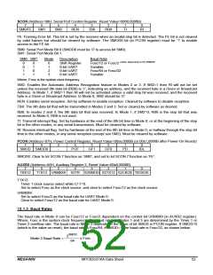
SCON (Address=98H, Serial Port Control Register, Reset Value=0000,0000B)
7
6
5
4
3
2
1
0
SM0/FE
SM1
SM2
REN
TB8
RB8
TI
RI
FE: Framing Error bit. This bit is set by the receiver when an invalid stop bit is detected. The FE bit is not cleared
by valid frames but should be cleared by software. The SMOD0 bit (in PCON register) must be ‘1’ to enable
access to the FE bit.
SM0: Serial Port Mode Bit 0 (SMOD0 must be ‘0’ to access bit SM0).
SM1: Serial Port Mode Bit 1.
SM0 SM1
Mode
Description
Shift Register
8-bit UART
9-bit UART
9-bit UART
Baud Rate
0
0
1
1
0
1
0
1
0
1
2
3
Fosc/12 or Fosc/2 *Note: dependent on bit URM0X6
Variable
Fosc/64 or Fosc/32
Variable
Where, Fosc is the system clock frequency.
SM2: Enables the Automatic Address Recognition feature in Modes 2 or 3. If SM2=1 then Rl will not be set
unless the received 9th data bit (RB8) is ‘1’, indicating an address, and the received byte is a Given or Broadcast
Address. In Mode 1, if SM2=1 then Rl will not be activated unless a valid stop bit was received, and the received
byte is a Given or Broadcast Address. In Mode 0, SM2 should be ‘0’.
REN: Enables serial reception. Set by software to enable reception. Cleared by software to disable reception.
TB8: The 9th data bit that will be transmitted in Modes 2 and 3. Set or cleared by software as desired.
RB8: In modes 2 and 3, the 9th data bit that was received. In Mode 1, if SM2=0, RB8 is the stop bit that was
received. In Mode 0, RB8 is not used.
Tl: Transmit interrupt flag. Set by hardware at the end of the 8th bit time in Mode 0, or at the beginning of the stop
bit in the other modes, in any serial transmission. Must be cleared by software.
Rl: Receive interrupt flag. Set by hardware at the end of the 8th bit time in Mode 0, or halfway through the stop bit
time in the other modes, in any serial reception (except see SM2). Must be cleared by software.
PCON (Address=87H, Power Control Register, Reset Value=00xx,0000B (or 00x1,0000B after Power-On Reset))
7
6
5
4
3
2
1
0
SMOD SMOD0
-
POF
GF1
GF0
PD
IDL
SMOD0: Clear to let SCON.7 function as ‘SM0’, and set to let SCON.7 function as ‘FE’.
AUXR2 (Address=A6H, Auxiliary Register 2, Reset Value=00x0,0000B)
7
6
5
4
3
2
1
0
T0X12
T1X12 URM0X6 S2TR S2SMOD S2TX12 S2CKOE T0CKOE
T1X12:
Timer 1 clock source select while C/-T=0.
Set to select Fosc as the clock source, and clear to select Fosc/12 as the clock source.
URM0X6:
Set to select Fosc/2 as the baud rate for UART Mode 0.
Clear to select Fosc/12 as the baud rate for UART Mode 0.
12.1.3 Baud Rates
The baud rate in Mode 0 can be Fosc/12 or Fosc/2 dependent on the control bit URM0X6 (in AUXR2 register).
Where, Fosc is the system clock frequency. The baud rates in Modes 1 and 3 are determined by the Timer 1 or
Timer 2 overflow rate. The baud rate in Mode 2 depends on the value of bit SMOD in PCON register. If SMOD=0
(which is the value on reset), the baud rate is Fosc/64; if SMOD=1, the baud rate is Fosc/32, as shown below.
2SMOD
Mode 2 Baud Rate =
x Fosc
64
MEGAWIN
MPC82G516A Data Sheet
52

 MEGAWIN [ MEGAWIN TECHNOLOGY CO., LTD ]