21 Power Saving Modes
The MPC82G516A has two power-saving modes and an 8-bit system clock prescaler to reduce the power
consumption. In the Idle mode the CPU is frozen while the peripherals and the interrupt system are still operating.
In the Power-down mode the RAM and SFRs’ value are saved and all other functions are inoperative; most
importantly, in the Power-down mode the device can be waked up by the external interrupts. And, the user can
further reduce the power consumption by using the 8-bit system clock prescaler to slow down the operating
speed.
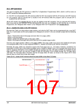
Registers PCON and PCON2 are related to power saving, as listed below.
PCON (Address=87H, Power Control Register, Reset Value=00xx,0000B (or 00x1,0000B after Power-On Reset))
7
6
5
4
3
2
1
0
SMOD SMOD0
-
POF
GF1
GF0
PD
IDL
GF1: General-purpose flag bit 1.
GF0: General-purpose flag bit 0.
PD: Power-Down mode bit. Setting this bit activates Power-Down mode.
IDL: Idle mode bit. Setting this bit activate Idle mode.
PCON2 (Address=C7H, Power Control Register 2, Reset Value=00x0,0000B)
7
6
5
4
3
2
1
0
-
-
-
-
-
SCKD2 SCKD1 SCKD0
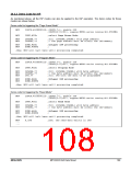
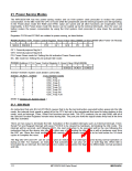
SCKD2~SCKD0: System clock divider control bits.
SCKD2 SCKD1 SCKD0
Fosc (System Clock)
OSC_Freq
0
0
0
0
1
1
1
1
0
0
1
1
0
0
1
1
0
1
0
1
0
1
0
1
OSC_Freq /2
OSC_Freq /4
OSC_Freq /8
OSC_Freq /16
OSC_Freq /32
OSC_Freq /64
OSC_Freq /128
(Refer to Section 22: System Clock.)
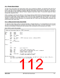
21.1 Idle Mode
An instruction that sets IDL bit (PCON.0) causes that to be the last instruction executed before going into the Idle
mode, the internal clock signal is gated off to the CPU but not to the peripherals that need to keep working in the
mode, such as Interrupt, Timer, Serial Port functions and so forth. The CPU contents, the on-chip RAM, and all of
the Special Function Registers remain intact during Idle. The port pins hold the logical states they had at the time
Idle was activated.
There are two ways to terminate the Idle. Activation of the enabled interrupts such as External Interrupt, Timer,
Serial Port and Keypad Interrupt will cause PCON.0 to be cleared by hardware, terminating the Idle mode. The
interrupt will be serviced, and following RETI, the next instruction to be executed will be the one following the
instruction that put the device into Idle. The other way of terminating the Idle mode is with a hardware reset from
the RST pin. Since the clock oscillator is still running, the hardware reset needs to be held active for 24 clock
cycles to complete the reset.
The flag bits GF0 and GF1 can be used to give an indication if an interrupt occurred during normal operation or
during an Idle. For example, an instruction that activates Idle can also set one or both flag bits. When Idle is
terminated by an interrupt, the interrupt service routine can examine the flag bits to differentiate normal operation
and Idle.
111
MPC82G516A Data Sheet
MEGAWIN

 MEGAWIN [ MEGAWIN TECHNOLOGY CO., LTD ]