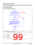
20.2.2.2 Flash Program Mode
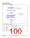
Figure 20-3. Flow Chart for “Flash Program”
Start
ISPEN=1 (enable ISP function),
and initialize ISPCR[2:0]
Refer to Table 20-2-1a
to initialize ISPCR[2:0]
IFMT=0x02 (select Program Mode)
Address=0x0000
Address=Address+1
IFADRH= High-byte of Byte_address
IFADRL= Low-byte of Byte_address
IFD=data (to be programmed)
SCMD=0x46, then SCMD=0xB9
(trigger ISP processing by sequential
writing)
NO
End of address?
YES
End
Demo code for triggering the “Program Mode”
MOV
ISPCR,#10000011b ;ISPCR.7=1, enable ISP
;ISPCR[2:0]=011, suppose MPC82-series running @11.0592MHz
MOV
IFMT,#02h
;select Program Mode
MOV
MOV
MOV
IFADRH,??
IFADRL,??
IFD,??
;fill [IFADRH,IFADRL] with byte address
;
;fill IFD with the data to be programmed
MOV
MOV
SCMD,#46h
SCMD,#0B9h
;trigger ISP processing
;
;Now, MCU will halt here until processing completed
MEGAWIN
MPC82G516A Data Sheet
100

 MEGAWIN [ MEGAWIN TECHNOLOGY CO., LTD ]