MX29LV800T/B
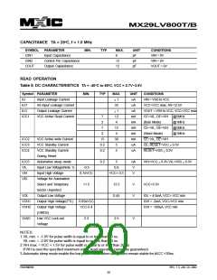
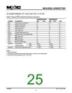
AC CHARACTERISTICS TA = -40oC to 85oC, VCC = 2.7V~3.6V
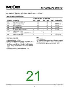
Table 9. READ OPERATIONS
29LV800T/B-70(R) 29LV800T/B-90
SYMBOL PARAMETER
MIN.
MAX.
70
MIN.
MAX.
90
UNIT
ns
CONDITIONS
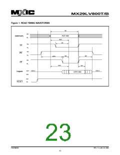
tRC
tACC
tCE
Read Cycle Time (Note 1)
Address to Output Delay
CE to Output Delay
70
90
ns
CE=OE=VIL
OE=VIL
70
90
ns
tOE
OE to Output Delay
30
35
ns
CE=VIL
tDF
OE High to Output Float (Note1)
Output Enable Read
0
0
25
0
30
ns
CE=VIL
tOEH
0
ns
Hold Time
Toggle and Data Polling 10
10
0
ns
tOH
Address to Output hold
0
ns
CE=OE=VIL
NOTE:
1. Not 100% tested.
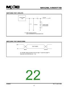
TEST CONDITIONS:
• Input pulse levels: 0V/3.0V.
• Input rise and fall times is equal to or less than 5ns.
• Outputload:1TTLgate+100pF(Includingscopeand
jig), for29LV800T/B-90. 1TTL gate+30pF(Including
scope and jig) for 29LV800T/B-70 and 29LV800T/B-
70R.
2. tDF is defined as the time at which the output achieves
the open circuit condition and data is no longer driven.
3.29LV800T/B-70R operates atVCC=3.0V~3.6V
• Reference levels for measuring timing: 1.5V.
P/N:PM0709
REV. 1.3, JAN. 24, 2002
21

 Macronix [ MACRONIX INTERNATIONAL ]