MX29LA129M H/L
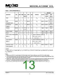
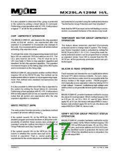
Table 1. BUS OPERATION (1)
Q8~Q15
Operation
CEx
OE# WE# RE-
SET#
WP# ACC
Address
Q0~Q7 Word
Mode
Byte
Mode
Read
enable
enable
enable
disable
L
H
H
X
H
H
H
H
X
X
X
AIN
AIN
AIN
X
DOUT
DOUT
Q8-Q15=
High Z
Write
L
(Note 3)
(Note 4) (Note 4 Q8-Q15=
High Z
(Program/Erase)
Accelerated
Program
L
(Note 3) VHH
(Note 4) (Note 4) Q8-Q15=
High Z
Standby
X
VCC±
0.3V
H
X
H
High-Z High-Z
High-Z
Output Disable
Reset
enable
X
H
X
H
H
X
L
X
X
H
X
X
X
X
X
High-Z High-Z
High-Z High-Z
High-Z
High-Z
X
L
Sector Group Protect enable
(Note 2)
VID
Sector Addresses, (Note 4)
A7=L,A4=L, A3=L,
A2=H,A1=L
X
Chip unprotect
(Note 2)
enable
X
H
X
L
VID
H
H
X
X
Sector Addresses, (Note 4)
A7=H, A4=L, A3=L,
A2=H, A1=L
X
X
Temporary Sector
Group Unprotect
X
VID
AIN
(Note 4) (Note 4)
High-Z
Legend:
L=Logic LOW=VIL, H=Logic High=VIH, VID=12.0±0.5V, VHH=12.0±0.5V, X=Don't Care, AIN=Address IN, DIN=Data IN,
DOUT=Data OUT
Notes:
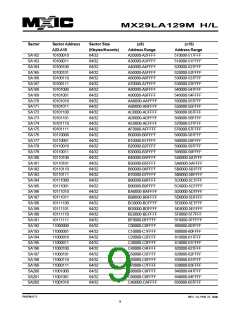
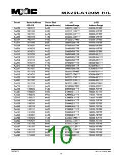
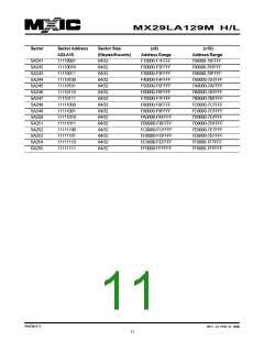
1. Address are A23:A1 in word mode; A23:A0 in byte mode. Sector addresses are A23:A16 in both modes.
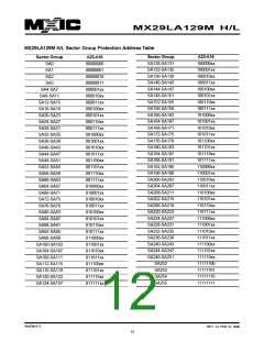
2. The sector group protect and chip unprotect functions may also be implemented via programming equipment.See
the "Sector Group Protection and Chip Unprotect" section.
3. If WP#=VIL, all the sectors remain protected.If WP#=VIH, all sectors protection depends on whether they were last
protected or unprotect using the method described in "Sector/ Sector Block Protection and Unprotect".
4. DIN or DOUT as required by command sequence, Data# polling or sector protect algorithm (see Figure 15).
P/N:PM1171
REV. 1.0, FEB. 27, 2006
13

 Macronix [ MACRONIX INTERNATIONAL ]