SMBus Level 2 Battery Charger
with Remote Sense
ADAPTER
INPUT
R2
100kΩ
R1
150kΩ
R13
CSSP
100kΩ
D1
RS1
10mΩ
DCIN
ACIN
SYSTEM
LOAD
C1
1μF
CSSN
V
CC
C
10μF
C
IN2
10μF
R3
49.9kΩ
IN1
C12
1μF
N
R12
33Ω
MAX8731A
LDO
LDO
C11
1μF
LDO
BST
R4
10kΩ
D2
N1, N2,: SI4800BDY
N3: SI4810BDY
ACOK
INPUT
VDD
V
DD
C10
0.1μF
R5
10kΩ
N1
R11
DHI
DHI
N2
KBC
1Ω
SCL
SDA
SCL
C2
0.1μF
LX
DLO
C9
220pF
R6
10kΩ
L1
4.3μH
N3
SDA
IINP
PGND
L1: SUMIDA
CEP125-4R3MC-U
RS2
10mΩ
CSIP
CSIN
R7
10kΩ
C3
0.1μF
V
OUT
CCV
CCI
C
10μF
OUT1
C
10μF
OUT2
R8
10kΩ
C5
0.01μF
BATSEL
FBSB
SELECTOR
R10
C4
0.01μF
100Ω
CCS
REF
FBSA
GND
C6
R9
100Ω
DAC
0.01μF
BP
C7
1μF
BATTERY
A
BATTERY
C8
0.1μF
B
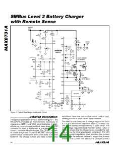
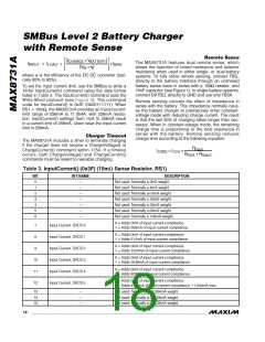
Figure 1. Typical Dual-Battery Application Circuit
amplifiers have low input-offset error ( 64µV typ),
allowing the use of small-valued sense resistors.
Detailed Description
The typical application circuit is shown in Figure 1. The
MAX8731A includes all the functions necessary to
charge Li+, NiMH, and NiCd smart batteries. A high-
efficiency, synchronous-rectified, step-down DC-DC
converter is used to implement a precision constant-
current, constant-voltage charger. The DC-DC convert-
er drives a high-side n-channel MOSFET and provides
synchronous rectification with a low-side n-channel
MOSFET. The charge current and input current-sense
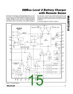
The MAX8731A features a voltage-regulation loop
(CCV) and two current-regulation loops (CCI and CCS).
The loops operate independently of each other. The
CCV voltage-regulation loop monitors either FBSA or
FBSB to ensure that its voltage never exceeds the volt-
age set by the ChargeVoltage() command. The CCI
battery current-regulation loop monitors the current
delivered to the selected battery to ensure that it never
exceeds the current limit set by the ChargeCurrent()
14 ______________________________________________________________________________________

 MAXIM [ MAXIM INTEGRATED PRODUCTS ]