Is o la t e d Tra n s fo rm e r Drive r
fo r P CMCIA Ap p lic a t io n s
MAX845
V
IN
5V
OUTPUT
5V @ 150mA
C1
CR1
V
CC
D1
V
CC
F / F
MAX845
OSC
Q
Q
N
C2
C3
T
FS
D2
FREQUENCY
SELECT
CR2
N
400kHz/
700kHz
SD
ON / OFF
GND2
GND1
ISO
GND
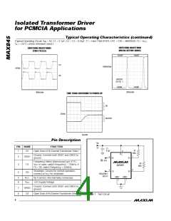
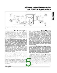
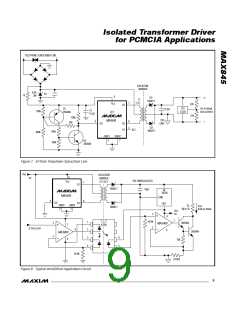
Figure 2. Detailed Block Diagram
Th e o ry o f Op e ra t io n
_______________De t a ile d De s c rip t io n
Figure 2 shows the MAX845 driving both a TGM-010P3
transformer with a center-tapped primary, and a sec-
ondary with a voltage-doubler rectifier topology. All of the
transformers driven by the MAX845 must have a center
The MAX845 is a tra ns forme r d rive r s p e c ific a lly
designed to provide isolated power for PCMCIA and
other height- and/or space-sensitive applications. It
drives a center-tapped transformer primary from a 5V
or 3.3V DC p owe r s up p ly. The s e c ond a ry c a n b e
wound to provide any isolated DC voltage needed at
power levels up to 750mW.
tap with V applied. Whenever one of the MAX845 out-
IN
puts (D1 or D2) goes low, the other goes to approximate-
ly double the supply voltage. A voltage is induced in the
secondary and the rectifier diodes steer the currents into
the a p propria te outp ut c a pa c itor. On a lte rna te ha lf
cycles, each capacitor is charged. The output voltage is
the sum of the voltages from each output capacitor. This
topology yields the simplest and smallest transformer
because the least number of secondary turns is required
for a given voltage.
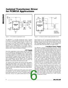
The 450kHz minimum switching frequency allows the
use of very thin transformers, making the MAX845 ideal
for PCMCIA and other space-limited applications. The
MAX845 is designed to drive a single transformer less
than 0.09 inches (2.3mm) in height, including package.
Further reduction down to 0.050 inches (1.27mm) can
be achieved using a transformer without a package.
__________Ap p lic a t io n s In fo rm a t io n
The MAX845 consists of an RC oscillator driving a pair
of N-channel power switches. The oscillator runs at
double the output frequency, driving a toggle flip-flop
to e nsure 50% duty c yc le to e a c h of the switc he s.
Internal circuitry ensures break-before-make action
between the two switches.
With the MAX845 transformer driver, designers have
the a d va nta g e s of p us h/p ull c onve rte r top olog y in
space-sensitive applications. The push/pull DC-DC
converter topology allows isolated multiple outputs,
step-up/step-down or inverted outputs, easier filtering
on the input and the output, and lower overall noise.
A low-current shutdown mode disables all internal cir-
cuitry, including the oscillator and both power switches.
Drive the shutdown pin (SD) high to shut down the part;
drive SD low for normal operation. The SD pin has no
internal default condition and must not be allowed to
float.
Is o la t e d P o w e r fo r P CMCIA Ap p lic a t io n s
Medical instrumentation, modems, and LAN-interface
cards often require isolated power supplies. One of the
best switching-regulator topologies for this application
is the push/pull forward-converting DC-DC power sup-
ply shown in Figures 3 and 4. Because the transformer
works in the forward mode (rather than the flyback
mode), its core does not store energy and, therefore,
can be small. Input and output capacitors can be small
because of the high-frequency and continuous-current
waveforms.
Most MAX845 applications will operate at high frequen-
cies. The frequency-select pin (FS) is pulled high or left
open (FS is internally pulled up to V ) to operate at a
CC
minimum of 450kHz. Pulling FS low selects the low-fre-
quency state.
_______________________________________________________________________________________
5

 MAXIM [ MAXIM INTEGRATED PRODUCTS ]