Is o la t e d Tra n s fo rm e r Drive r
fo r P CMCIA Ap p lic a t io n s
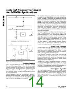
The simplest voltage regulator is the shunt zener shown
R
S
in Figure 12. The series resistor (R ) value should be as
S
high as possible to still deliver the maximum expected
load current with minimum input voltage. Be sure that no
ratings are exceeded at maximum input voltage and
minimum load current conditions; under such conditions,
the zener diode may have to dissipate much more power
than the load. Alternatively, start with the maximum allow-
able zener dissipation and select the series resistor
under light-load, high-line conditions. Then verify that
there is sufficient output current available with worst-
case low input voltage.
MAX845
SIMPLE SHUNT ZENER
R
S
22k
22k
For better regulation than the simple shunt zener, con-
sider a shunt regulator IC such as the TL431. This
device behaves like a zener diode whose voltage can
be programmed by a resistor ratio. It can be used as a
stand-alone device or can be boosted above its 150mA
maximum rating without compromising its accuracy by
adding a discrete PNP transistor, as shown in Figure 12.
TL431
5V OUTPUT
PROGRAMMABLE-IC SHUNT REGULATOR (STAND ALONE)
The input power of a shunt regulator is nearly indepen-
dent of load, so efficiency at light loads tends to be
worse than it would be with a series regulator.
R
S
Ou t p u t Filt e r Ca p a c it o r
Ceramic capacitors can be used as output capacitors
because of the lower level of output ripple current. In
applications where output ripple is not critical, a 0.33µF
chip or ceramic capacitor is normally sufficient. Refer to
Table 3 for suggested capacitor suppliers.
1k
22k
22k
2N2907
5V OUTPUT
TL431
In applications sensitive to output-ripple noise, the out-
put filter capacitor (C2) should have a low equivalent
series resistance (ESR) and a low equivalent series
inductance (ESL), and its capacitance should remain
fairly constant over temperature.
PROGRAMMABLE-IC SHUNT REGULATOR WITH DISCRETE PNP
Sprague 595D surface-mount solid tantalum capacitors
and Sanyo OS-CON through-hole capacitors are recom-
mended, if space allows, due to their extremely low ESR.
Capacitor ESR usually rises at low temperatures, but OS-
CON capacitors provide very low ESR below 0°C.
Figure 12. Shunt-Regulator Circuits
Ou t p u t Re g u la t o r
Sinc e the outp ut volta g e is not re g ula te d a g a ins t
changes in the input voltage or load current, an output
voltage regulator may be needed. A series linear regu-
lator gives good performance and reasonably good
efficiency at low cost. A shunt regulator costs less,
occupies less space, and gives adequate performance
for some applications.
In p u t Byp a s s Ca p a c it o r
The input bypass capacitor (C1) is not critical. Unlike
switching regulators, the MAX845’s supply current is
fairly constant, and is therefore less dependent on the
inp ut b yp a s s c a p a c itor. A low-c os t 0.33µF c hip or
c e ra mic c a p a c itor is norma lly s uffic ie nt for inp ut
bypassing.
Se rie s re g ula tors s uc h a s the MAX666, MAX667,
MAX882/MAX883/MAX884, or MAX603/MAX604 simpli-
fy designs. Just select one with the desired output volt-
age and current capability, and connect it.
14 ______________________________________________________________________________________

 MAXIM [ MAXIM INTEGRATED PRODUCTS ]