5 V/1 2 V/1 5 V o r Ad ju s t a b le , High-Effic ie nc y,
Low I , Ste p-Up DC-DC Controlle rs
Q
0–MAX73
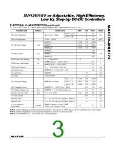
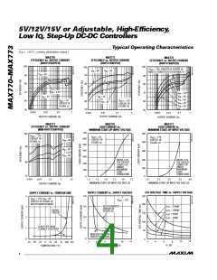
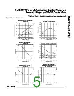
____________________________Typ ic a l Op e ra t in g Ch a ra c t e ris t ic s (c o n t in u e d )
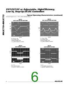
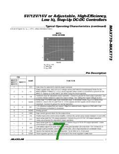
(Circuit of Figure 2a, T = +25°C, unless otherwise noted.)
A
MAX770
EXITING SHUTDOWN
A
B
0
0
200µs/div
V
IN
= 3V, I = 0.5A
OUT
A: SHDN, 2V/div
B: V , 2V/div
OUT
______________________________________________________________P in De s c rip t io n
PIN
MAX770
MAX771 MAX773
MAX772
NAME
FUNCTION
1
—
EXT
V+
Gate drive for external N-channel power transistor
Power-supply input. Also acts as a voltage-sense point when in bootstrapped mode for the
MAX770/MAX771/MAX772, or as a shunt regulator when SGND is connected to ground for the
MAX773. Bypass to SGND with 0.1µF when using the shunt regulator.
2
3
Feedback input for adjustable-output operation. Connect to ground for fixed-output operation. Use
a resistor divider network to adjust the output voltage. See Setting the Output Voltage section.
3
4
5
6
7
8
FB
Active-high TTL/CMOS logic-level shutdown input. In shutdown mode, V
is a diode drop
OUT
below V+ (due to the DC path from V+ to the output) and the supply current drops to 5µA
maximum. Connect to ground for normal operation.
1.5V reference output that can source 100µA for external loads. Bypass to GND with 0.1µF.
The reference is disabled in shutdown.
SHDN
REF
6
7
8
—
9
AGND
GND
CS
Analog ground
High-current ground return for the output driver
11
Positive input to the current-sense amplifier. Connect the current-sense resistor between CS and GND.
Input sense point for 12V-output operation. Connect V
Leave unconnected for adjustable-output operation.
to V12 for 12V-output operation.
OUT
—
—
—
1
2
4
V12
V5
Input sense point for 5V-output operation. Connect V
to V5 for 5V-output operation. Leave
OUT
unconnected for adjustable-output operation.
Low-battery output is an open-drain output that goes low when LBI is less than 1.5V. Connect to V+
through a pull-up resistor. Leave floating if not used. LBO is high impedance in shutdown mode.
LBO
—
—
5
LBI
Input to the internal low-battery comparator. Tie to GND or V+ if not used.
10
SGND
Shunt regulator ground. Leave unconnected if the shunt regulator is not used.
_______________________________________________________________________________________
7

 MAXIM [ MAXIM INTEGRATED PRODUCTS ]