SOT23, 3V/5V, Single-Supply, Rail-to-Rail
Instrumentation Amplifiers
END-POINT LINE
V
OUT
IDEAL TRANSFER
FUNCTION (LINE)
B
V
OUT
V
OUT2
Z
E
IDEAL LINE
ACTUAL CURVE
V
IN1
V
IN
0
V
V
IN
IN2
0
V
OUT1
A
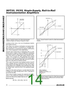
Figure 3. Transfer Function of an Ideal Instrumentation
Amplifier (Straight Line Passing Through the Origin)
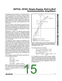
Figure 4. Typical Transfer Function for a Real Instrumentation
Amplifier
Looking at this curve, one can immediately identify
three types of errors.
ACTUAL CURVE
B
V
First, there is an obvious nonlinearity (curvature) when
this transfer function is compared to a straight line.
More deviation is measured as greater nonlinearity
error. This is explained in more detail below.
OUT
END-POINT LINE
IDEAL LINE SHIFT
D
Z
E
Second, even if there was no nonlinearity error, i.e., the
actual curve in Figure 4 was a straight line connecting
end points A and B, there exists an obvious slope devi-
ation from that of an ideal gain slope (drawn as the
“ideal” line in Figure 4). This rotational error (delta
slope) is a measure of how different the actual gain
NL+
V
IN
0
(G ) is from the expected ideal gain (G and is called
A
I)
gain error (GE) (see the equation below).
Third, even if the actual curve between points A and B
was a straight line (no nonlinearity error) and had the
same slope as the ideal gain line (no gain error), there
is still another error called the end-point offset error (OE
on vertical axis), since the line is not passing through
the origin.
C
A
NL-
SLOPE
SLOPE
= IDEAL GAIN = G
= ACTUAL GAIN = G
(CD)
I
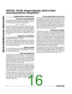
Figure 5 is the same as Figure 4, but the ideal line (CD)
is shifted up to pass through point E (the Y intercept of
end-points line AB).
(AB)
A
GAIN ERROR (%) = GE (%) = 100 X (G - G ) / G
I
OFFSET
(END POINT)
NL- = NL+
A
I
= OE
This is done to better visualize the rotational error (GE),
which is the difference between the slopes of end
points line AB and the shifted ideal line CD.
Figure 5. Typical Transfer Function for a Real Instrumentation
Amplifier (Ideal Line (CD) Is Shifted by the End-Points Offset
(OE) to Visualize Gain Error)
Mathematically:
GE (%) = 100 x (G - G ) / G
I
A
I
14 ______________________________________________________________________________________

 MAXIM [ MAXIM INTEGRATED PRODUCTS ]