SOT23, 3V/5V, Single-Supply, Rail-to-Rail
Instrumentation Amplifiers
levels. In these cases, as the output approaches either
supply, accuracy may degrade, especially under heavy
output loading.
Input Common-Mode and Output
Reference Ranges
MAX4460/MAX4461/MAX4462 have an input common-
mode range of 100mV below the negative supply to
1.7V below the positive supply.
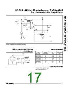
Shutdown Mode
The MAX4461U/T/H features a low-power shutdown
mode. When the SHDN pin is pulled low, the internal
transconductance and amplifier blocks are switched off
and supply current drops to typically less than 0.1µA
(Figure 1).
The output reference voltage of MAX4462U/T/H is set by
REF and ranges from 100mV above the negative supply
to 1.7V below the positive supply. For maximum voltage
swing in a bipolar operation, connect REF to VDD/2.
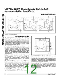
The output voltages of the MAX4460 and MAX4461U/
T/H are referenced to ground. Unlike the traditional
three-op-amp configuration of common instrumentation
amplifiers, the MAX4460/MAX4461/MAX4462 have
In shutdown, the amplifier output is high impedance.
The output transistors are turned off, but the feedback
resistor network remains connected. If the external load
is referenced to GND, the output drops to approximate-
ly GND in shutdown. The output impedance in shut-
down is typically greater than 100kΩ. Drive SHDN high
ground-sensing capability (or to V
in dual-supply
SS
configuration) in addition to the extremely high input
impedances of MOS input differential pairs.
or connect to V
for normal operation.
CC
Input Differential Signal Range
The MAX4460/MAX4461/MAX4462 feature a proprietary
input structure optimized for small differential signals.
The unipolar output of the MAX4460/MAX4461 is nomi-
nally zero-for-zero differential input. However, these
devices are specified for inputs of 50mV to 100mV for
the unity-gain devices, 20mV to 100mV for gain of 10
devices, and 2mV to 48mV for gain of 100 devices. The
MAX4460/MAX4461 can be used with differential inputs
approaching zero, albeit with reduced accuracy.
A User Guide to Instrumentation
Amplifier Accuracy Specifications
As with any other electronic component, a complete
understanding of instrumentation amplifier specifica-
tions is essential to successfully employ these devices
in their application circuits. Most of the specifications
for these differential closed-loop gain blocks are similar
to the well-known specifications of operational ampli-
fiers. However, there are a few accuracy specifications
that could be confusing to first-time users. Therefore,
some explanations and examples may be helpful.
The bipolar output of the MAX4462 allows bipolar input
ranges. The output voltage is equal to the reference
voltage for zero differential input. The MAX4462 is
specified for inputs of 100mV for the unity gain and
gain of 10 devices, and 20mV for gain of 100 devices.
The gain of 100 devices (MAX4462H) can be operated
beyond 20mV signal provided the reference is chosen
for unsymmetrical swing.
Accuracy specifications are measurements of close-
ness of an actual output response to its ideal
expected value. There are three main specifications
in this category:
ꢁ
ꢁ
ꢁ
Gain error
Gain nonlinearity error
Offset error
Output Swing
The MAX4460/MAX4461/MAX4462 are designed to
have rail-to-rail output voltage swings. However,
depending on the selected gain and supply voltage
(and output reference level of the MAX4462), the rail-to-
rail output swing is not required.
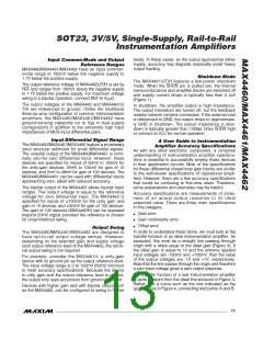
In order to understand these terms, we must look at the
transfer function of an ideal instrumentation amplifier. As
expected, this must be a straight line passing through
origin with a slope equal to the ideal gain (Figure 3). If
the ideal gain is equal to 10 and the extreme applied
input voltages are -100mV and +100mV, then the value
of the output voltages are -1V and +1V, respectively.
Note that the line passes through the origin and therefore
a zero input voltage gives a zero output response.
For example, consider the MAX4461U, a unity-gain
device with its ground pin as the output reference level.
The input voltage range is 0 to 100mV (50mV minimum
to meet accuracy specifications). Because the device
is unity gain and the output reference level is ground,
the output only sees excursions from ground to 100mV.
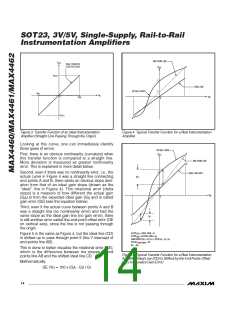
The transfer function of a real instrumentation amplifier
is quite different from the ideal line pictured in Figure 3.
Rather, it is a curve such as the one indicated as the
typical curve in Figure 4, connecting end points A and B.
Devices with higher gain and with bipolar output such
as the MAX4462, can be configured to swing to higher
______________________________________________________________________________________ 13

 MAXIM [ MAXIM INTEGRATED PRODUCTS ]