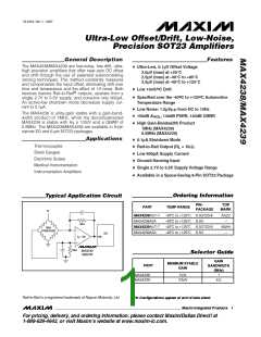
Ultra-Low Offset/Drift, Low-Noise,
Precision SOT23 Amplifiers
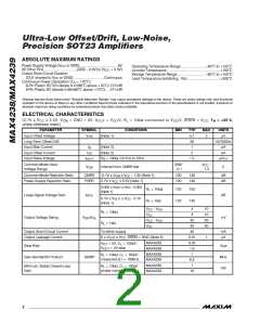
ABSOLUTE MAXIMUM RATINGS
Power-Supply Voltage (V
to GND).......................................6V
°
°
°
°
°
CC
Operating Temperature Range..........................-40 C to +125 C
All Other Pins .................................(GND - 0.3V) to (V
Output Short-Circuit Duration
+ 0.3V)
CC
Junction Temperature ......................................................+150 C
°
Storage Temperature Range..............................-65 C to +150 C
(OUT shorted to V
Continuous Power Dissipation (T = +70 C)
6-Pin Plastic SOT23 (derate 9.1mW/ C above +70 C).727mW
8-Pin Plastic SO (derate 5.88mW/ C above +70 C).....471mW
or GND) ...............................Continuous
CC
Lead Temperature (soldering, 10s) .................................+300 C
°
A
°
°
°
°
Stresses beyond those listed under “Absolute Maximum Ratings” may cause permanent damage to the device. These are stress ratings only, and functional
operation of the device at these or any other conditions beyond those indicated in the operational sections of the specifications is not implied. Exposure to
absolute maximum rating conditions for extended periods may affect device reliability.
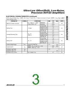
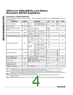
ELECTRICAL CHARACTERISTICS
°
(2.7V ≤ V
≤ 5.5V, V
= GND = 0V, V
= V /2, R = 10kΩ connected to V /2, SHDN = V , T = +25 C,
CC
CM
OUT
CC
L
CC
CC
A
unless otherwise noted.)
PARAMETER
SYMBOL
CONDITIONS
MIN
TYP
0.1
50
1
MAX
UNITS
Input Offset Voltage
Long-Term Offset Drift
Input Bias Current
Input Offset Current
Input Noise Voltage
V
(Note 1)
2
µV
OS
nV/1000hr
I
(Note 2)
(Note 2)
pA
pA
B
I
2
OS
e
R = 100Ω, 0.01Hz to 10Hz
1.5
µV
P-P
nP-P
S
Common-Mode Input
Voltage Range
GND
- 0.1
V
1.3
-
CC
V
Inferred from CMRR test
V
CM
Common-Mode Rejection Ratio
Power-Supply Rejection Ratio
CMRR
PSRR
-0.1V ≤ V
≤ V
- 1.3V (Note 1)
CC
120
120
140
140
dB
dB
CM
2.7V ≤ V
≤ 5.5V (Note 1)
CC
0.05V ≤ V
(Note 1)
≤ V - 0.05V
CC
OUT
R = 10kΩ
125
125
150
145
L
Large-Signal Voltage Gain
Output Voltage Swing
A
dB
VOL
0.1V ≤ V
≤ V
- 0.1V
CC
OUT
R = 1kΩ
L
(Note 1)
V
V
V
V
- V
4
4
10
10
50
50
CC
OL
CC
OL
OH
OH
R = 10kΩ
L
V
/V
mV
OH OL
- V
35
35
40
0.01
0.35
1.6
1
R = 1kΩ
L
Output Short-Circuit Current
Output Leakage Current
To either supply
0 ≤ V ≤ V , SHDN = GND (Note 2)
mA
µA
1
OUT
CC
MAX4238
MAX4239
MAX4238
MAX4239
MAX4238
MAX4239
V
V
= 5V, C = 100pF,
L
CC
Slew Rate
V/µs
MHz
V/V
= 2V step
OUT
R = 10kΩ, C = 100pF,
L
L
Gain-Bandwidth Product
GBWP
measured at f = 100kHz
6.5
1
Minimum Stable Closed-Loop
Gain
R = 10kΩ, C = 100pF,
L
L
phase margin = 60o
10
2
_______________________________________________________________________________________

 MAXIM [ MAXIM INTEGRATED PRODUCTS ]