Low-Cost Multichemistry Battery Chargers
Setting the Battery Regulation Voltage
Detailed Description
The MAX1908/MAX8724 use a high-accuracy voltage
The MAX1908/MAX8724 include all the functions neces-
regulator for charging voltage. The VCTL input adjusts
the charger output voltage. VCTL control voltage can
sary to charge Li+ batteries. A high-efficiency synchro-
nous-rectified step-down DC-DC converter controls
vary from 0 to V
, providing a 10% adjustment
REFIN
charging voltage and current. The device also includes
input source current limiting and analog inputs for set-
ting the charge current and charge voltage. Control
charge current and voltage using the ICTL and VCTL
inputs, respectively. Both ICTL and VCTL are ratiometric
with respect to REFIN, allowing compatibility with D/As
or microcontrollers (µCs). Ratiometric ICTL and VCTL
improve the accuracy of the charge current and voltage
range on the V
regulation voltage. By limiting the
BATT
adjust range to 10% of the regulation voltage, the exter-
nal resistor mismatch error is reduced from 1% to
0.05% of the regulation voltage. Therefore, an overall
voltage accuracy of better than 0.7% is maintained
while using 1% resistors. The per-cell battery termina-
tion voltage is a function of the battery chemistry.
Consult the battery manufacturer to determine this volt-
age. Connect VCTL to LDO to select the internal default
set point by matching V
to the reference of the
REFIN
host. For standard applications, internal set points for
ICTL and VCTL provide 3A charge current (with 0.015Ω
sense resistor), and 4.2V (per cell) charge voltage.
Connect ICTL and VCTL to LDO to select the internal set
points. The MAX1908 safely conditions overdischarged
cells with 300mA (with 0.015Ω sense resistor) until the
battery-pack voltage exceeds 3.1V × number of series-
connected cells. The SHDN input allows shutdown from
a microcontroller or thermistor.
setting V
= 4.2V × number of cells, or program the
BATT
battery voltage with the following equation:
V
VCTL
V
= CELLS × 4V + 0.4 ×
BATT
V
REFIN
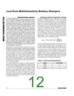
CELLS is the programming input for selecting cell count.
Connect CELLS as shown in Table 1 to charge 2, 3, or 4
Li+ cells. When charging other cell chemistries, use
CELLS to select an output voltage range for the charger.
The DC-DC converter uses external N-channel
MOSFETs as the buck switch and synchronous rectifier
to convert the input voltage to the required charging
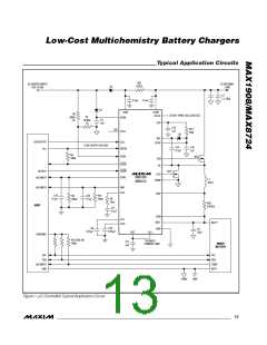
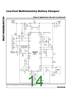
current and voltage. The Typical Application Circuit
shown in Figure 1 uses a µC to control charging cur-
rent, while Figure 2 shows a typical application with
charging voltage and current fixed to specific values
for the application. The voltage at ICTL and the value of
RS2 set the charging current. The DC-DC converter
generates the control signals for the external MOSFETs
to regulate the voltage and the current set by the VCTL,
ICTL, and CELLS inputs.
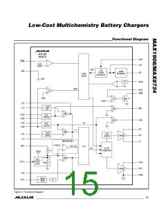
The internal error amplifier (GMV) maintains voltage
regulation (Figure 3). The voltage error amplifier is
compensated at CCV. The component values shown in
Figures 1 and 2 provide suitable performance for most
applications. Individual compensation of the voltage reg-
ulation and current-regulation loops allows for optimal
compensation (see the Compensation section).
Table 1. Cell-Count Programming
The MAX1908/MAX8724 feature a voltage-regulation
loop (CCV) and two current-regulation loops (CCI and
CCS). The CCV voltage-regulation loop monitors BATT
to ensure that its voltage does not exceed the voltage
set by VCTL. The CCI battery current-regulation loop
monitors current delivered to BATT to ensure that it
does not exceed the current limit set by ICTL. A third
loop (CCS) takes control and reduces the battery-
charging current when the sum of the system load and
the battery-charging input current exceeds the input
current limit set by CLS.
CELLS
CELL COUNT
GND
2
3
4
Float
V
REFIN
12 ______________________________________________________________________________________

 MAXIM [ MAXIM INTEGRATED PRODUCTS ]