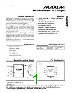
USB-Powered Li+ Charger
providing 500mA, and an unpowered USB hub is limit-
ed to only 100mA.
Detailed Description
Charger-Control Circuitry
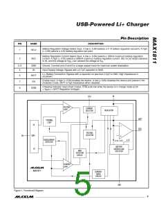
The voltage/current regulator consists of a voltage con-
trol loop, a current control loop, and a thermal control
loop (Figure 1). Use the SELV input to set the battery
regulation voltage to a 4.1V or 4.2V single Li+ cell. The
current and thermal loops are internally compensated
and require no external compensation. The outputs
from all loops drive an internal linear regulator. The
thermal loop modulates the current loop by limiting the
charge current if the die temperature exceeds +125°C.
The MAX1811 is in current mode when the BATT volt-
age is below the regulation set point and in voltage
mode when the BATT voltage is near the regulation set
point. The CHG output indicates whether the part is in
current mode (CHG = low) or voltage mode (CHG =
Drive SELI low to set the charge current to the 100mA
mode. Use a 10k pulldown resistor to ground on SELI,
if necessary, to ensure that the MAX1811 defaults to
the 100mA mode in the event that no logic signal is
present. Drive SELI high to increase the charge current
to the 500mA mode only if the polled USB port can pro-
vide the required current.
Thermal-Control Circuitry
The thermal loop limits the MAX1811 die temperature to
+125°C by reducing the charging current as neces-
sary. The MAX1811 can operate normally with the ther-
mal loop active. This is not a fault condition and can be
used continuously. The power dissipated by the inter-
✕
nal power FET is determined by (V - V
)
I
.
IN
BATT
CHG
high impedance). Battery voltages less than 2.5V acti-
vate a 43mA preconditioning mode (CHG = high
impedance). Normal charging resumes when the bat-
tery voltage exceeds 2.5V.
The power dissipation rating for the thermally enhanced
8-pin SO package is 1.4W at +50°C ambient (assuming
a 1in2 PC board radiating area), which is the maximum
ambient temperature at which most Li+ battery manu-
facturers allow charging. The 1.4W power dissipation
may never be reached due to the MAX1811’s thermal
regulation loop.
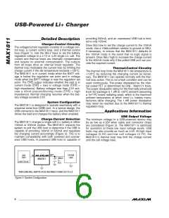
System Configuration
The MAX1811 is designed to operate seamlessly with a
universal serial bus (USB) port. In a typical design, the
USB connects to the MAX1811 input, and the MAX1811
drives the load and charges the battery when enabled.
Applications Information
USB Output Voltage
The minimum voltage to a USB-powered device may
be as low as 4.35V when cable and connector drops
are considered (Figure 3). The MAX1811 is optimized
for operation at these low input voltage levels. USB
hubs may also provide as much as 5.5V. At high input
voltages (5.5V) and low cell voltages (2.7V), the
MAX1811’s thermal loop may limit the charge current
until the cell voltage rises.
Charge-Current Selection
The MAX1811 charges a single cell Li+ battery in either
100mA or 500mA modes. The MAX1811 expects the
system to poll the USB host to determine if the USB is
capable of providing 100mA or 500mA and regulates
the charging current accordingly (Figure 2). This is to
maintain compatibility with both powered and unpow-
ered USB hosts. A powered USB host is capable of
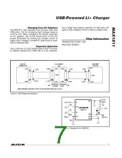
BATT
SYSTEM
LOAD
USB*
PORT
IN
SINGLE
Li+
CELL
MAX1811
4.35V TO 5.5V
*WHEN USING WALL ADAPTER, IN VOLTAGE RANGE IS FROM 4.35V TO 6.5V.
Figure 2. System Configuration
6
_______________________________________________________________________________________

 MAXIM [ MAXIM INTEGRATED PRODUCTS ]