USB-Powered Li+ Charger
Pin Description
PIN
NAME
DESCRIPTION
Battery Regulation Voltage-Select Input. A low (< 0.8V) selects a 4.1V battery regulation set point. A high
(> 2.0V) selects a 4.2V battery regulation set point.
1
SELV
Battery Regulation Current-Select Input. A low (< 0.8V) selects a 100mA maximum battery regulation
current. A high (> 2.0V) selects a 500mA maximum battery regulation current. SELI is not diode clamped
2
SELI
to IN, and the voltage at V
can exceed the voltage at V .
IN
SELI
3, 6
4
GND
IN
Ground. Connect pins 3 and 6 to a large copper trace for maximum power dissipation.
Input Supply Voltage. Bypass with a 4.7µF capacitor to GND.
Li+ Battery Connection. Bypass with a capacitor no less than 2.2µF to GND. High impedance in
shutdown.
5
7
8
BATT
EN
Enable Input. A high (> 2.0V) enables the device. A low (< 0.8V) disables the device and places it into
shutdown mode. BATT is high impedance when disabled.
Charging Indicator Open-Drain Output. CHG pulls low while the device is in charge mode (2.5V
CHG
< V
< BATT Regulation Voltage).
BATT
IN
SELI
VOLTAGE
LOOP
CURRENT
SELECTOR
REGULATOR
BATT
CHG
THERMAL
LOOP
3V
VOLTAGE
SELECTOR
BIAS
EN
OVERCURRENT
DETECTOR
4.7V
(2.5V, 4.2V)
BATTERY
2V
OVERVOLTAGE
DETECTOR
MAX
DETECTOR
CIRCUIT
CURRENT
LOOP
MAX1811
CURRENT-
SENSE
CIRCUIT
GND
SELV
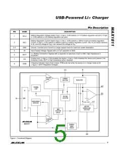
Figure 1. Functional Diagram
_______________________________________________________________________________________
5

 MAXIM [ MAXIM INTEGRATED PRODUCTS ]