MAX14921 Evaluation Kit
Evaluates: MAX14921
Table 2. EV Kit Control Section Details (Figure 6) (continued)
ITEM
LABEL
READ/WRITE
DESCRIPTION
Setsꢀtheꢀdelayꢀbetweenꢀacquisitionsꢀofꢀaꢀsetꢀofꢀcellꢀvoltages.ꢀForꢀexample,ꢀatꢀtheꢀ
default 10ms, the device samples cell voltages 100 times per second. This entry is
ignored by the application when it updates the cell voltages directly on the window.
However,ꢀwhenꢀstreamingꢀdataꢀtoꢀaꢀfile,ꢀthisꢀparameterꢀsetsꢀhowꢀoftenꢀaꢀnewꢀdataꢀ
setꢀisꢀwrittenꢀtoꢀtheꢀfile.ꢀTheꢀrepeatꢀtimeꢀmustꢀbeꢀatꢀleastꢀ1msꢀgreaterꢀthanꢀtheꢀ
sample time. If not, the repeat time is about 1ms greater than the sample time.
4
RepeatꢀTime
Write
5
6
Product
Read
Read
This value is obtained from the device when the EV kit is attached to the PC.
This value is obtained from the device when the EV kit is attached to the PC.
DieꢀRevision
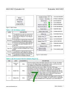
This status indicator is updated regularly once the EV kit is attached to the PC.
Aꢀredꢀindicatorꢀmeansꢀthatꢀtheꢀinternalꢀ5VꢀLDOꢀisꢀunableꢀtoꢀprovideꢀtheꢀcorrectꢀ
voltageꢀtoꢀtheꢀdeviceꢀorꢀtoꢀtheꢀattachedꢀexternalꢀcircuitry.
7
VA UV
Read
Readyꢀtoꢀ
Operate
This status bit is updated regularly from the device when the EV kit is attached to
the PC. A red indicator means that there is something wrong with the device.
8
9
Read
Read
Action
Thermal
Shutdown
This status bit is updated continuously from the device when the EV kit is attached
to the PC. A red indicator means that the device is too hot.
Click this control button to toggle the EN pin on the device and enable or disable
the IC.
10
Power Down
Click this control button to implement open-wire detection as detailed in the First
Method of Open-Wire DetectionꢀsectionꢀinꢀtheꢀMAX14920/MAX14921ꢀICꢀdataꢀ
sheet. This detection is not continuous and happens once each time this control
isꢀpushed.ꢀItꢀupdatesꢀtheꢀopen-wireꢀ(OW)ꢀindicatorsꢀinꢀtheꢀcellꢀvoltageꢀreadoutꢀ
section of the application window. Indicators are dimmed green or red when this
information is considered stale.
DetectꢀOpenꢀ
11
12
Action
Action
Wires
Click this control button to implement the offset calibration feature, as detailed in
the Buffer Amplifier Offset CalibrationꢀsectionꢀinꢀtheꢀMAX14920/MAX14921ꢀICꢀ
data sheet. The output buffer offset is minimized once calibration is complete.
OffsetꢀCal
Click this control button to enable continuous reading of the cell voltages, the
cellꢀU/OVꢀbits,ꢀandꢀtheꢀT1–T3ꢀvoltages.ꢀTheꢀapplicationꢀupdatesꢀ6ꢀtoꢀ7ꢀtimesꢀperꢀ
second unless the sample time is set too high.
13
14
15
Measure
Action
Action
Clickꢀthisꢀcontrolꢀbuttonꢀtoꢀdisableꢀcontinuousꢀreading.ꢀOnlyꢀoneꢀsetꢀofꢀdataꢀisꢀ
measured and presented in the application window when this button is pushed.
MeasureꢀOnce
This global control either disables or enables cell balancing for all cells whose
balanceꢀcheckboxesꢀareꢀchecked.ꢀCellꢀbalancingꢀcanꢀbeꢀindividuallyꢀenabledꢀwithꢀ
theꢀbalanceꢀcheckboxes.
Balance
Enable/Disable
Selection
MaximꢀIntegratedꢀꢀ
│ 8
www.maximintegrated.com

 MAXIM [ MAXIM INTEGRATED PRODUCTS ]