MAX14921 Evaluation Kit
Evaluates: MAX14921
MAX14523A power switches (U113 and U114) auto-
matically power the EV kit from either USB connector.
A MAX8880 linear regulator (U109) provides a clean 3.3V
supply for the microprocessor (U101) and related circuitry.
The microprocessor uses the Q101 and Q102 circuit to
switchꢀinꢀorꢀoutꢀaꢀ1.5kΩꢀpullupꢀresistorꢀonꢀtheꢀUSBꢀDPꢀ
line, to implement USB suspend mode.
Analog Cell Voltage Acquisition
The heart of the EV kit is the analog signal path.
Theꢀ MAX14921ꢀ (U1)ꢀ operatesꢀ inꢀ twoꢀ majorꢀ phases.ꢀ Inꢀ
the first phase, cell voltages present at the cell stack
connectorꢀ(P2)ꢀareꢀacquiredꢀontoꢀtheꢀsamplingꢀcapacitorsꢀ
C1–C16ꢀthroughꢀ100ΩꢀseriesꢀresistorsꢀR1ꢀandꢀR40–R54.ꢀ
These resistors limit the current during fault conditions.
The default GUI sampling time of 4ms is optimized to
work with these resistors and capacitors. All cell voltages
are captured simultaneously.
To avoid any damage to the PC in the case of accidental
miswiring,ꢀ theꢀ cellꢀ voltageꢀ acquisitionꢀ circuitryꢀ isꢀ elec-
trically isolated from the microprocessor circuitry and
USB interface. Two MAX14850 digital isolators (U107,
U108) provide this isolation for the SPI and other digital
signals and a MAX256 transformer driver (U111), along
with transformer T101 provide an isolated supply to a
MAX8880 linear regulator (U110). The MAX8880 provides
a clean 5V supply for all circuits in the analog capture
path,ꢀ withꢀ theꢀ exceptionꢀ ofꢀ theꢀ internalꢀ supplyꢀ ofꢀ theꢀ
MAX14921 and the analog supply of the MAX11163 ADC,
which power from the MAX14921’s internal 5V regulator.
In the second phase, captured cell voltages are level shift-
ed down and presented to the ADC (U3) for conversion.
Aꢀsmallꢀcircuitꢀ(R2ꢀandꢀC25)ꢀfiltersꢀtheꢀsignalꢀbetweenꢀtheꢀ
MAX14921 and the MAX11163 ADC. To improve accu-
racy,ꢀ anꢀ externalꢀ voltageꢀ reference,ꢀ MAX6126ꢀ (U2),ꢀ isꢀ
used to provide a stable reference to the ADC.
Auxiliary Inputs (T1–T3)
The MAX14921 also includes three general-purpose
analog inputs, ranging from 0 to 5V that can be multi-
plexedꢀtoꢀtheꢀADCꢀforꢀconversion.ꢀMeasuringꢀtemperatureꢀ
throughꢀ inexpensiveꢀ thermistorsꢀ isꢀ oneꢀ commonꢀ useꢀ forꢀ
theseꢀ extraꢀ inputs.ꢀ Inputsꢀ T2ꢀ andꢀ T3ꢀ onꢀ theꢀ EVꢀ kitꢀ areꢀ
presetꢀtoꢀacceptꢀaꢀ10kΩꢀthermistor.ꢀTheꢀMAX9620ꢀopꢀampꢀ
(U4)ꢀbuffersꢀtheꢀreferenceꢀvoltageꢀtoꢀ10kΩꢀpullupꢀresistorsꢀ
(R59ꢀandꢀR60),ꢀwhileꢀfilteringꢀisꢀdoneꢀwithꢀR56,ꢀR57,ꢀC27,ꢀ
and C28.
Detailed Description of Software
The Windows-based graphical-user interface (GUI)
application is simple to use and demonstrates all the
important features of the device. The application auto-
matically detects the presence of an EV kit. If the applica-
tion is run before any EV kit is attached, the fields appear
mostlyꢀ blank,ꢀ asꢀ seenꢀ inꢀ Figureꢀ 3.ꢀ Onceꢀ anꢀ EVꢀ kitꢀ isꢀ
detected, fields are automatically filled in.
InputꢀT1ꢀisꢀuncommitted.ꢀTheꢀpullupꢀresistorꢀ(R61)ꢀforꢀthisꢀ
inputꢀisꢀnotꢀinstalled,ꢀandꢀdifferentꢀfilterꢀcomponentsꢀ(R58ꢀ
and C29) are used, optimized for faster input signals.
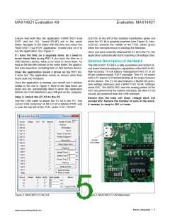
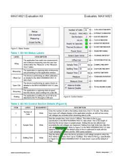
Status Section
Figure 5 shows the “Status” window, located at the
bottom-right corner of the application window. It indicates
the status of the EV kit connection to the PC.
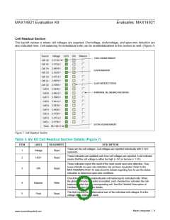
Cell Balancing
TheꢀEVꢀkitꢀincludesꢀtransistorsꢀQ1–Q16ꢀandꢀ33Ωꢀpowerꢀ
resistors for cell-balancing applications. These transistors
can be enabled or disabled, using the SPI interface, in
any combination at any time for passive cell-balancing
purposes.
Theꢀtextꢀinꢀtheꢀwindowꢀindicatesꢀwhetherꢀtheꢀapplicationꢀ
sees an EV kit or not. It indicates either “EVK Attached,”
or “EVK Detached.”
The third line details the real-time instructions to the EV kit
fromꢀtheꢀapplication.ꢀTableꢀ1ꢀincludesꢀaꢀdetailedꢀexplana-
tion for each label.
Power and Isolation
The EV kit accepts power from either USB con-
nector, P102 or P105. To use the supplied GUI,
connect to P102. P105 is used only when reprogram-
ming microprocessor U101. Because a different protocol
is used for reprogramming, the GUI does not recognize
the EV kit if the USB cable is plugged in to P105. Two
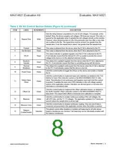
Control Section
Much of the control and status information for the EV kit is
available in the top-right section of the application. Figure
6 and Table 2 detail the available controls and indicators.
MaximꢀIntegratedꢀꢀ
│ 6
www.maximintegrated.com

 MAXIM [ MAXIM INTEGRATED PRODUCTS ]