RF Coax Connectors
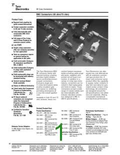
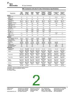
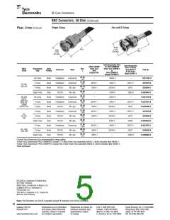
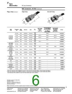
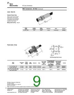
BNC Connectors (50 ohm/75 ohm) Performance Specifications
Commercial
O Crimp
& Hex Crimp
50 Ohms
Commercial
O Crimp
& Hex Crimp
75 Ohms
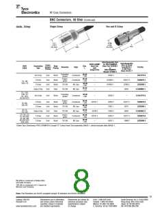
Single
Crimp
(MIL Type)
Category B
O Crimp
(MIL Type)
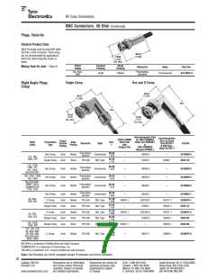
Straight
Solder
Clamp
Right-Angle
Solder
Clamp
Commercial PC
Board
50 & 75 Ohms
Commercial
Solder
50 Ohm Jacks
Characteristics
Electrical
Impedance, Nom.
50
50
50
50
50
75
50 & 75
500
50 & 75
500
(Ohms)
Working Voltage
(Volts RMS)
500
500
500
500
500
500
Contact Resistance
(Milliohms)
Inner: 1.5
Outer: 0.3
Inner: 1.5
Outer: 0.2
Inner: 1.5
Outer: .20
Inner: 1.5
Outer: .20
Inner: 2.0
Outer: 1.0
Inner: 2.0
Outer: 2.0
Inner: 6/1.5
Outer: 3/0.2
Inner: 2.75
Outer: 1.0
Initial Insulation Resistance
(Megohms)
5000
1500
375
5000
1500
375
5000
1500
375
5000
1500
375
5000
1500
375
5000
1500
375
5000
1500
—
5000
1500
375
—
Dielectric Withstanding
Voltage (VAC)
Corona Level at 70,000 ft.
(Volts, RMS)
RF Leakage, Max.
(dB)
-55 at
2-3 GHz
-55 at
2-3 GHz
-55 at
2-3 GHz
-55 at
2-3 GHz
-55 at
1-2 GHz
—
—
RF Insertion Loss,
Max. (dB)
0.2 at
3 GHz
0.2 at
3 GHz
0.3 at
3 GHz
0.2 at
3 GHz
0.15 at
2 GHz
—
—
—
Frequency Range
(GHz)
0-4 and
0-2
0-2.5
1.35
0-4
0-4
0-4
0-4
0-2
0-4
—
VSWR in Frequency
Range Max.
1.30
1.30
1.35
1.30
1.30
—
Mechanical
Force to Engage (lbs. [N])/couple,
(in-lbs. [N-M]) max.
13.3/11.12
[3/2.5]
13.3/11.12
[3/2.5]
13.3/.028
[3/2.5]
13.3/.028
[3/2.5]
26.7/26.69
[6/6.0]
26.7/26.69
[6/6.0]
—
—
—
—
Coupling Nut Retention,
Min. N [lbs.]
444.8
[100]
444.8
[100]
444.8
[100]
444.8
[100]
266.9
[60]
266.9
[60]
Cable Retention,
N [lbs.]
266.9 [60]
(RG58C/U)
266.9 [60]
(RG58C/U)
177.9 [40]
(RG58C/U)
177.9 [40]
(RG58C/U)
266.9 [60]
(RG58C/U)
266.9 [60]
(RG58C/U)
266.9 [60]
(PCB Ret)
—
Durability (Cycles)
500
500
500
500
500
500
500
500
Jam Nut Mounting Torque,
Max. [N•m] (in. lbs.)
25
[2.8]
25
[2.8]
25
[2.8]
25
[2.8]
25
[2.8]
253/124
[2.8/1.4]
25
[2.8]
—
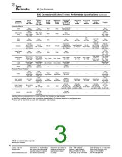
Environmental
Temperature Range,
Operating (C°)
-65 to +1651
-55 to +852
-65 to +85
-65 to +165
-65 to +165
-55 to +85
-55 to +85
-55 to +85
-65 to +165
MIL-STD-202 MIL-STD-202 MIL-STD-202
MIL-STD-202
Method 204
Cond. B
MIL-STD-1344
Method 2005
Cond. III
MIL-STD-202
Method 204
Cond. B
MIL-STD-202
Method 204
Cond. B
MIL-STD-202
Method 201A
Vibration
Method 204
Cond. B
Method 204
Cond. B
Method 204
Cond. B
MIL-STD-202 MIL-STD-202 MIL-STD-202
MIL-STD-202
Method 213
Cond. G
MIL-STD-1344
Method 2004
MIL-STD-202
Method 213
MIL-STD-202
Method 213
MIL-STD-202
Method 213
Physical Shock
Thermal Shock
Method 213
Method 213
Method 213
Cond. G
Cond. G, 50 G’s Cond. G, 50 G’s
Cond. G, 100 G’s
Cond. I, 100 G’s
Cond. I or A, 50 G’s Cond. I, 100 G’s
MIL-STD-1344
Method 1003
Cond. A
MIL-STD-202 MIL-STD-202 MIL-STD-202
Method 107 Method 107 Method 107
MIL-STD-202
Method 107
MIL-STD-202
Method 107
MIL-STD-202
Method 107
MIL-STD-202
Method 107
MIL-STD-1344
Method 1002
Type II
Moisture
Resistance
MIL-STD-202 MIL-STD-202 MIL-STD-202
Method 106 Method 106 Method 106
MIL-STD-202
Method 106
MIL-STD-202
Method 106
MIL-STD-202
Method 106
MIL-STD-202
Method 106
MIL-STD-202 MIL-STD-202 MIL-STD-202
MIL-STD-202
Method 101
Cond. B
MIL-STD-1344
Method 1001
Cond. B
MIL-STD-202
Method 101
Cond. B
MIL-STD-202
Method 101
Cond. B
MIL-STD-202
Method 101
Cond. B
Salt Spray
Method 101
Cond. B
Method 101
Cond. B
Method 101
Cond. B
Product
Specification
108-12044
108-12047
108-12002
108-12020
—
—
108-12095
108-12078
108-12079
1Assembled to cable with polytetrafluorethylene dielectric.
2Assembled to cable with polyethylene dielectric.
3For Metal Threads
4For Polyester Threads
45
Catalog 1307191
Revised 3-07
Dimensions are in millimeters
and inches unless otherwise
specified. Values in brackets
are standard equivalents.
Dimensions are shown for
reference purposes only.
Specifications subject
to change.
USA: 1-800-522-6752
South America: 55-11-2103-6000
Hong Kong: 852-2735-1628
Japan: 81-44-844-8013
Canada: 1-905-470-4425
Mexico: 01-800-733-8926
C. America: 52-55-1106-0803
www.tycoelectronics.com
UK: 44-8706-080-208

 MACOM [ Tyco Electronics ]