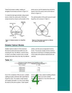
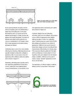
These focal smears overlap, creating an
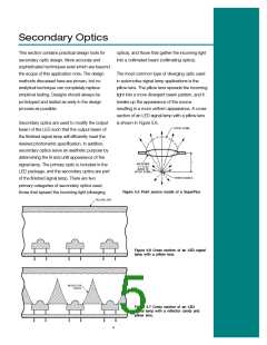
points source; and the aperture size should be
equal to that of the epoxy dome at its base as
shown in Figure 5.5.
elongated focal smear as shown in Figure 5.4.
To create the best approximation using a point
source model, the center point of the focal
smears should be chosen as the location of the
The optimal position of the point source for each
SuperFlux LED is shown in Table 5.1.
Figure 5.3 Internal structure of a SuperFlux
LED.
Figure 5.4 Focal smear produced by reflected
and reflected-refracted light.
Detailed Optical Models
Detailed optical models of LEDs include all
the internal optical structures within the LED
including the chip, the reflector, and the dome.
In order to accurately construct such a model,
detailed information about the chip, the reflector
surface, and the epoxy encapsulant must be
known. The process usually involves a tedious
trial and error technique of changing parameters
in the model until empirical measurements are
matched.
Table 5.1
Position of Point Source for SuperFlux LEDs
SuperFlux LED
Part Number
Position of Point Source
“Z” (mm)
HPWA-MxOO
HPWA-Dx00
HPWT-Mx00
HPWT-DxOO
1.03
1.13
0.99
1.17
Due to the complexity of this process, Lumileds
Lighting provides customers with rayset files for
SuperFlux LEDs. The raysets contain spacial
and angular information on a set of rays exiting
the device at the dome surface. These raysets
can be used by many optical-modeling software
packages. Contact your local Lumileds
Applications Engineer for more information and
copies of the raysets.
4

 LUMILEDS [ LUMILEDS LIGHTING COMPANY ]