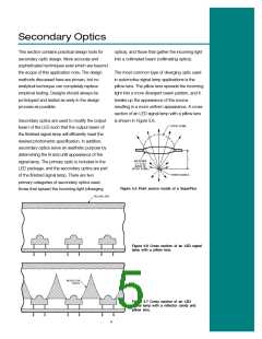
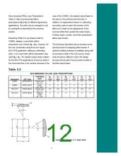
Pillow Lens Design
Consider a pillow lens where the half-angle
subtended by and individual pillow is A as
shown in Figure 5.9, and the input beam has
a half-angle divergence B as shown in Figure
5.10.
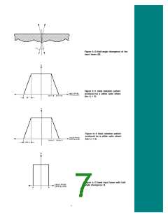
The ideal radiation patterns shown in Figures
5.11 and 5.12 assume that the input beam has
a box-like radiation pattern as shown in Figure
5.13.
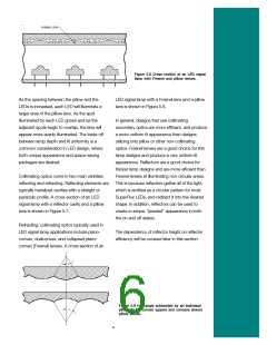
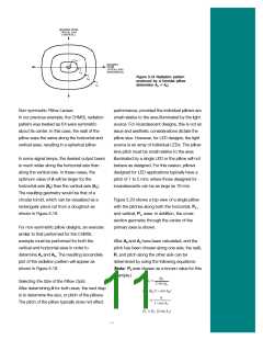
However, in actual cases the input beam will
have the characteristics of the Cosine form of
the Lambertian as shown in Figure 5.14.
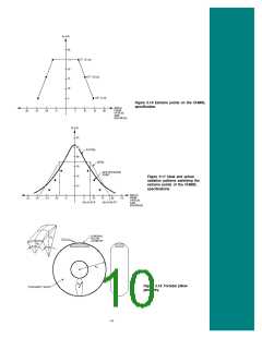
The ideal radiation pattern generated would be
as shown in Figure 5.11, where n is the index of
refraction of the pillow lens material. It should be
noted that Figure 5.11 is applicable when B is
smaller than A(n-1). This assumption is true for
most LED applications using a collimating
secondary optic.
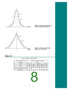
The differences between the ideal, box-like input
beam, and the more common Lambertian input
beam result in changes to the final radiation
pattern as shown in Figure 5.15. The magnitude
of this deviation in the radiation pattern can be
estimated by evaluating the magnitude of the
input beam’s deviation from the ideal. This
deviation from the ideal should be considered
in the design of the pillow lens.
In cases where B is larger than A(n-1), which is
often the case when the LED is used without a
collimating optic, the ideal radiation pattern
would be as shown in Figure 5.12.
Design Case—Pillow Design for an LED CHMSL
Consider the case where a collimating secondary optic is
Using a Center High Mounted Stop Lamp (CHMSL) as an
example, we can see how the design techniques discussed
previously can be used to determine an optimum value of A.
The minimum intensity values for a CHMSL are shown in
Table 5.2.
used producing a beam divergence of B = 5° (B < A(n-1))
and similar to that shown in Figure 5.14. The pillow lens
material is Polycarbonate which has an index of refraction of
1.59 (n = 1.59). The ideal CHMSL radiation pattern is shown
in Figure 5.17 such that all the extreme points of the
specification are satisfied. Figure 5.17 shows the predicted
actual radiation pattern.
As a conservative estimate, we can treat this pattern as
symmetric about the most extreme points. The extreme
points are those with the highest specified intensity values
at the largest angular displacements from the center of the
pattern. These points are shown in italics in Table 5.2. The
angular displacement of a point from the center is found by
taking the square root of the sum of the squares of the
angular displacements in the vertical and horizontal
directions. A point at 10R and 5U would have an angular
displacement from the center of:
From Figure 5.17, we can see that A(n-1)-B = 8°?and
A(n-1)+B = 18°; therefore, A = 22°. The value of A selected
will determine how much spread the pillow optic adds to the
input beam.
These points are charted on an intensity versus angle plot in
Figure 5.16.
9

 LUMILEDS [ LUMILEDS LIGHTING COMPANY ]