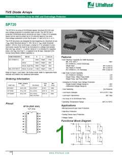
TVS Diode Arrays
Electronic Protection Array for ESD and Overvoltage Protection
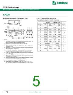
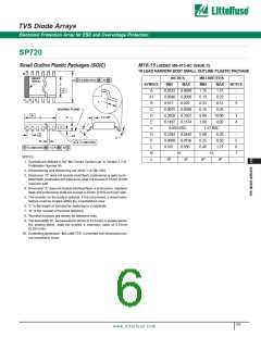
SP720
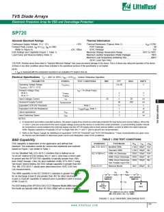
Absolute Maximum Ratings
Thermal Information
Continuous Supply Voltage, (V+) - (V-). . . . . . . . . . . . . . . . . . . . . . . . . +35V
Forward Peak Current, I to V , I to GND
(Refer to Figure 6) . . . . .. . . . . . . . . . . . . . . . . . . . . . . . . . . . . ±2A, 100µs
ESD Ratings and Capability (Figure 1, Table 1)
Thermal Resistance (Typical, Note 1). . . . . . . . . . . . . . . . . . . . . θ (oC/W)
JA
PDIP Package . . . . . . . . . . . . . . . . . . . . . . . . . . . . . . . . . . . . . . . . . . . . .90
SOIC Package . . . . . . . . . . . . . . . . . . . . . . . . . . . . . . . . . . . . . . . . . . . 130
Maximum Storage Temperature Range . . . .. . . . . . . . . . . . . . . -65oC to 150oC
Maximum Junction Temperature (Plastic Package) . . . . . . . . . . . . . . . . . . . . . 150oC
Maximum Lead Temperature (Soldering 10s) . . . . . . . . .. . . . . . .. . . . . . . . . .300oC
(SOIC Lead Tips Only)
IN
CC IN
Load Dump and Reverse Battery (Note 2)
CAUTION: Stresses above those listed in “Absolute Maximum Ratings” may cause permanent damage to the device. This is a stress only rating and operation of the device
at these or any other conditions above those indicated in the operational sections of this specification is not implied.
NOTE:
1. θ is measured with the component mounted on an evaluation PC board in free air.
JA
Electrical Specifications
T
= -40oC to 105oC; V = 0.5V
IN
, Unless Otherwise Specified
CC
A
PARAMETER
SYMBOL
TEST CONDITIONS
MIN
TYP
MAX
UNITS
Operating Voltage Range,
V
-
2 to 30
-
V
SUPPLY
V
= [(V+) - (V-)]
SUPPLY
Forward Voltage Drop:
IN to V-
IN to V+
I
= 1A (Peak Pulse)
IN
V
-
-
2
2
-
-
V
V
FWDL
V
FWDH
Input Leakage Current
Quiescent Supply Current
Equivalent SCR ON Threshold
Equivalent SCR ON Resistance
Input Capacitance
I
-20
5
50
1.1
1
20
nA
nA
V
IN
QUIESCENT
5
I
-
-
-
-
-
200
Note 3
/I ; Note 3
-
-
-
-
V
Ω
FWD FWD
C
3
pF
ns
IN
Input Switching Speed
NOTES:
t
2
ON
2. In automotive and battery operated systems, the power supply lines should be externally protected for load dump and reverse battery. When the
V+ and V- pins are connected to the same supply voltage source as the device or control line under protection, a current limiting resistor should
be connected in series between the external supply and the SP720 supply pins to limit reverse battery current to within the rated maximum
limits. Bypass capacitors of typically 0.01µF or larger from the V+ and V- pins to ground are recommended.
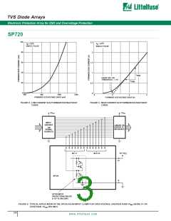
3. Refer to the Figure 3 graph for definitions of equivalent “SCR ON Threshold” and “SCR ON Resistance.” These characteristics are given here
for thumb-rule information to determine peak current and dissipation under EOS conditions.
TABLE 1. ESD TEST CONDITIONS
ESD Capability
ESD capability is dependent on the application and defined test
standard. The evaluation results for various test standards and methods
based on Figure 1 are shown in Table 1.
STANDARD
TYPE/MODE
R
C
±V
D
D
D
MIL STD 3015.7 Modified HBM
Standard HBM
1.5kΩ 100pF 15kV
1.5kΩ 100pF 6kV
For the “Modified” MIL-STD-3015.7 condition that is defined as an
“in-circuit” method of ESD testing, the V+ and V- pins have a return path
to ground and the SP720 ESD capability is typically greater than 15kV
from 100pF through 1.5kΩ. By strict definition of MIL-STD-3015.7 using
“pin-to-pin” device testing, the ESD voltage capability is greater than 6kV.
The MIL-STD-3015.7 results were determined from AT&T ESD Test
Lab measurements.
IEC 61000-4-2
HBM, Air Discharge
330Ω 150pF 15kV
HBM, Direct Discharge 330Ω 150pF 4kV
HBM, Direct Discharge, 330Ω 150pF 8kV
Two Parallel Input Pins
EIAJ IC121
Machine Model
0kΩ 200pF 1kV
R
D
R
1
The HBM capability to the IEC 61000-4-2 standard is greater than 15kV
for air discharge (Level 4) and greater than 4kV for direct discharge
(Level 2). Dual pin capability (2 adjacent pins in parallel) is well in excess
of 8kV (Level 4).
CHARGE
SWITCH
DISCHARGE
SWITCH
C
D
IN
H.V.
SUPPLY
°±V
For ESD testing of the SP720 to EIAJ IC121 Machine Model (MM) standard,
the results are typically better than 1kV from 200pF with no series resistance.
DUT
D
IEC 1000-4-2: R 50 to 100MΩ
1
MIL STD 3015.7:R 1 to 10MΩ
1
FIGURE 1. ELECTROSTATIC DISCHARGETEST
229
www. lit t elf us e. c om

 LITTELFUSE [ LITTELFUSE ]