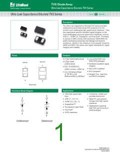
TVS Diode Array
Ultra Low Capacitance Discrete TVS Series
Thermal Information
Absolute Maximum Ratings
Symbol
Parameter
Value
Units
Parameter
StorageTemperature Range
Rating
Units
IPP
TOP
Peak Current (tp=8/20μs)
OperatingTemperature
StorageTemperature
2.0
A
-55 to 150
150
°C
°C
-30 to 85
-55 to 150
°C
°C
Maximum JunctionTemperature
TSTOR
Maximum LeadTemperature
(Soldering 20-40s)
260
°C
CAUTION: Stresses above those listed in “Absolute Maximum Ratings” may cause permanent damage to the
device. This is a stress only rating and operation of the device at these or any other conditions above those
indicated in the operational sections of this specification is not implied.
Unidirectional Electrical Characteristics - (TOP=25°C)
Parameter
Input Capacitance
Test Conditions
Min
Typ
Max
Units
@ VR = 0V, f = 3GHz
VBR @ IT=1mA
0.20
9.00
0.25
pF
V
Breakdown Voltage
Reverse Working Voltage
Reverse Leakage Current
Clamping Voltage
7. 0
50
V
IL @ VRWM=5.0V
VCL @ IPP=2.0A
25
nA
V
9.20
IEC61000-4-2 (Contact)
IEC61000-4-2 (Air)
20
20
ESD Withstand Voltage
kV
Bidirectional Electrical Characteristics - (TOP=25°C)
Parameter
Input Capacitance
Test Conditions
Min
Typ
0.10
9.80
Max
Units
pF
V
@ VR = 0V, f = 3GHz
VBR @ IT=1mA
0.13
Breakdown Voltage
Reverse Working Voltage
Reverse Leakage Current
Clamping Voltage
-7.0
7. 0
50
V
IL @ VRWM=5.0V
VCL @ IPP=2.0A
25
nA
V
10.0
IEC61000-4-2 (Contact)
IEC61000-4-2 (Air)
20
20
ESD Withstand Voltage
kV
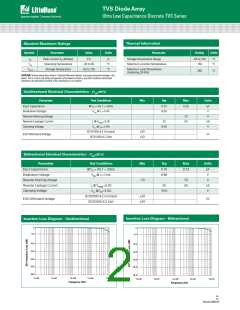
Insertion Loss Diagram - Bidirectional
Insertion Loss Diagram - Unidirectional
0
0
-5.0
-5.0
-10.0
-15.0
-10.0
-15.0
-20.0
-25.0
-20.0
-25.0
-30.0
-30.0
1.E+06
1.E+07
1.E+08
1.E+09
1.E+10
1.E+06
1.E+07
1.E+08
1.E+09
1.E+10
Frequency (Hz)
Frequency (Hz)
Ultra Low Capactance DiscreteTVS series
© 2019 Littelfuse, Inc.
Specifications are subject to change without notice.
Revised: 08/22/19

 LITTELFUSE [ LITTELFUSE ]