PULSEGUARD® SUPPRESSOR
SURFACE MOUNT ESD SUPPRESSORS
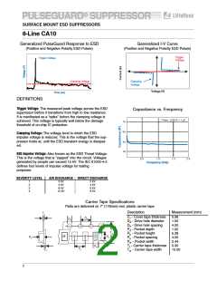
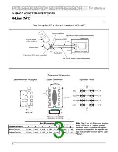
8-Line CA10
Test Set-up for IEC 61000-4-2 Waveform, 2kV-15kV
Device under test
Tek P6156 Probe (Voltage measurement)
Faraday cage
Brown tip (x100)
KeyTek pulser
2,000- 15,000 V
x10
Ground return
x10
Tektronic TDS 684B
Blue tip (x10)
.5 ohm shunt (10-5 ohms in parallel)
Tek P6156 Probe (Current measurement)
Reference Schematics:
Recommended Pad Layout:
Device Dimensions:
Equivalent Circuit:
10
0.007
0.083"
d
9
8
1
2
3
4
0.043"
e
0.008
0.198"
7
6
a
5
a
c
b
*Dimension 'a' is: 0.026"
*Dimension 'b' is: 0.015"
Note: Pins 5 and 10 (Common) are typ-
ically connected to chassis ground.
However since PulseGuard suppres-
sors are bi-directional, the system volt-
age bus can also be used as the ESD
“dump”.
Pad Dimensions (in.)
Solder Method
Wave Solder
a
b
c
d
e
f
g
0.036 0.060 0.119 0.047 0.043 0.030 0.198
Reflow Solder
0.025 0.050 0.101 0.051 0.043 0.030 0.191
3

 LITTELFUSE [ LITTELFUSE ]