PULSEGUARD® SUPPRESSOR
SURFACE MOUNT ESD SUPPRESSORS
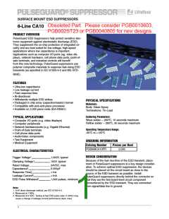
8-Line CA10
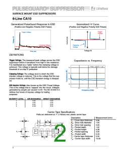
Generalized PulseGuard Response to ESD
Generalized I-V Curve
(Positive and Negative Polarity ESD Pulses)
(Positive and Negative Polarity ESD Pulses)
Trigger
Voltage
Trigger Voltage
Clamping Voltage
Clamping
Voltage
Voltage (V)
Time (ns)
DEFINITIONS
Trigger Voltage: The measured peak voltage across the ESD
suppressor before it transitions from high to low resistance.
It is manifested as a “spike” before the clamping voltage is
achieved. This voltage is typically well below the damage
threshold of on-chip IC protection.
Capacitance vs. Frequency
** Note: 1,000 fF = 1 pF
70
60
Clamping Voltage: The voltage level to which the ESD
impulse voltage is reduced. This is the voltage that the sup-
pressor holds at, until the ESD transient energy is dissipat-
ed.
50
40
ESD Impulse Voltage: Also known as the ESD Threat Voltage.
This is the voltage that is “zapped” into the circuit. Voltages
generated by people can exceed 15 kV. The IEC 61000-4-2
defines four levels of impulse voltage for testing
purposes:
0.5
1.0
1.5
2.0
Frequency (GHz)
SEVERITY LEVEL
AIR DISCHARGE
DIRECT DISCHARGE
1
2
3
4
2 kV
4 kV
8 kV
15 kV
2 kV
4 kV
6 kV
8 kV
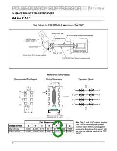
Carrier Tape Specifications
Parts are delivered on 7” (178mm) reel, plastic carrier tape
Description
Measurement (mm)
Tt
Ct - Cover tape thickness
0.06
1.50
4.00
1.02
5.38
4.00
2.44
0.30
12.00
Ds
Dd
Dd - Drive hole diameter
Ds - Drive hole spacing
Pd - Pocket depth
Ph - Pocket height
Ps - Pocket spacing
Pw - Pocket width
+
+
+
+
Tw
+
+
+
Ph
Pd
Tt - Carrier tape thickness
Tw - Carrier tape width
Pw
Ps
Ct
2

 LITTELFUSE [ LITTELFUSE ]