LTC2996
applicaTions inForMaTion
Output Noise Filtering
When V
falls below 1.093V, UT is pulled low. Once the
PTAT
temperature rises again and V
reaches 1.093V plus
PTAT
The V
output typically exhibits 0.6mV RMS (0.25°C
PTAT
a hysteresis of 20mV, UT is released high again. Accord-
ingly, OT is pulled low if temperature increases to 90°C as
RMS) noise. For applications which require lower noise,
digital or analog averaging can be applied to the output.
Choose the averaging time according to:
V
reaches 1.453V and is released high if V
drops
PTAT
PTAT
again below 1.433V.
2
[
]
°
0.01 C Hz
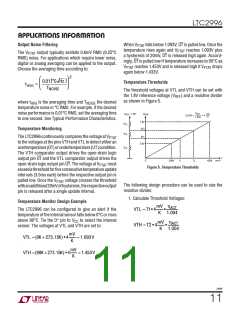
Temperature Thresholds
tAVG
=
T
NOISE
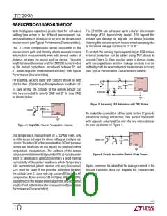
The threshold voltages at VTL and VTH can be set with
the 1.8V reference voltage (V ) and a resistive divider
REF
as shown in Figure 5.
where t
is the averaging time and T
the desired
NOISE
AVG
temperature noise in °C RMS. For example, if the desired
noise performance is 0.01°C RMS, set the averaging time
to one second. See Typical Performance Characteristics.
η
mV
K
V
= 1.8V
V
ACT
REF
PTAT
SLOPE =
• 4
1.004
1.8V
VT2
R
TC
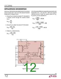
Temperature Monitoring
R
TB
VT1
The LTC2996 continuously compares the voltage at V
PTAT
to the voltages at the pins VTH and VTL to detect either an
overtemperature(OT)orundertemperature(UT)condition.
The VTH comparator output drives the open-drain logic
output pin OT and the VTL comparator output drives the
O.8V
R
TA
T
2996 F05
O
200K
T
T
450K
1
2
open-drain logic output pin UT. The voltage at V
must
PTAT
Figure 5. Temperature Thresholds
exceedathresholdforfiveconsecutivetemperatureupdate
intervals (3.5ms each) before the respective output pin is
pulled low. Once the V
voltage crosses the threshold
PTAT
The following design procedure can be used to size the
resistive divider.
withanadditional20mVofhysteresis,therespectiveoutput
pin is released after a single update interval.
1. Calculate Threshold Voltages:
Temperature Monitor Design Example
mV η
ACT
VTL = T1• 4
•
The LTC2996 can be configured to give an alert if the
K
1.004
temperature of the internal sensor falls below 0°C or rises
+
above 90°C. Tie the D pin to V to select the internal
CC
mV η
ACT
VTH = T2 • 4
•
sensor. The voltages at VTL and VTH are set to:
K
1.004
mV
K
VTL =(0K + 273.15K) • 4
VTH =(90K + 273.15K) • 4
= 1.093V
= 1.453V
mV
K
2996f
11

 Linear [ Linear ]