LTC2309
APPLICATIONS INFORMATION
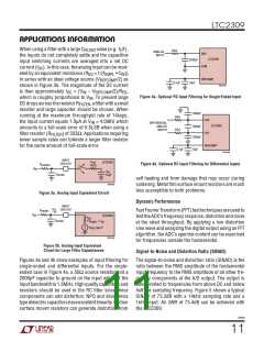
When using a filter with a large C
value (e.g. 1μF),
50Ω
FILTER
ANALOG
INPUT
CH0
the inputs do not completely settle and the capacitive
LTC2309
2000pF
10μF
input switching currents are averaged into a net DC
COM
current (I ). In this case, the analog input can be mod-
DC
eled by an equivalent resistance (R = 1/(f
in series with an ideal voltage source (V
• C ))
REFCOMP
EQ
SMPL
IN
/2) as
REFCOMP
0.1μF
2309 F04a
shown in Figure 3b. The magnitude of the DC current
is then approximately I = (V – V /2)/R ,
DC
IN
REFCOMP
EQ
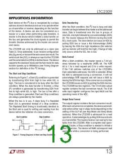
Figure 4a. Optional RC Input Filtering for Single-Ended Input
which is roughly proportional to V . To prevent large
IN
DCdropsacrosstheresistorR
,afilterwithasmall
FILTER
resistor and large capacitor should be chosen. When
1000pF
50Ω
running at the maximum throughput rate of 14ksps,
CH0
the input current equals 1.5μA at V = 4.096V, which
DIFFERENTIAL
IN
LTC2309
ANALOG
INPUTS
1000pF
1000pF
amounts to a full-scale error of 0.5LSB when using a
50Ω
CH1
filter resistor (R
) of 333ꢀ. Applications requiring
FILTER
lower sample rates can tolerate a larger filter resistor
REFCOMP
for the same amount of full-scale error.
0.1μF
10μF
2309 F04b
INPUT
CH0-CH7
R
LTC2309
ON
Figure 4b. Optional RC Input Filtering for Differential Inputs
R
SOURCE
100Ω
V
IN
C
IN
C
FILTER
55pF
self heating and from damage that may occur during
soldering. Metal film surface mount resistors are much
less susceptible to both problems.
2309 F03a
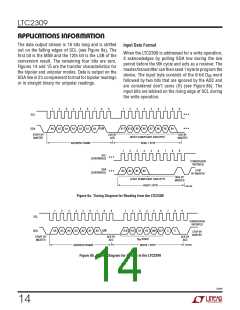
Figure 3a. Analog Input Equivalent Circuit
Dynamic Performance
INPUT
I
DC CH0-CH7
R
FILTER
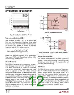
FastFourierTransform(FFT)testtechniquesareusedto
testtheADC’sfrequencyresponse,distortionandnoise
at the rated throughput. By applying a low distortion
sine wave and analyzing the digital output using an FFT
algorithm, the ADC’s spectral content can be examined
for frequencies outside the fundamental.
V
IN
LTC2309
R
EQ
SMPL
C
FILTER
1/(f
• C )
IN
+
V
/2
REFCOMP
–
2309 F03b
Figure 3b. Analog Input Equivalent
Circuit for Large Filter Capacitances
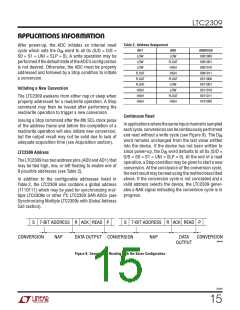
Signal-to-Noise and Distortion Ratio (SINAD)
Figures 4a and 4b show examples of input filtering for
The signal-to-noise and distortion ratio (SINAD) is the
single-ended and differential inputs. For the single- ratio between the RMS amplitude of the fundamental
ended case in Figure 4a, a 50ꢀ source resistor and a
input frequency to the RMS amplitude of all other fre-
2000pF capacitor to ground on the input will limit the quency components at the A/D output. The output is
inputbandwidthto1.6MHz.Highqualitycapacitorsand band-limited to frequencies from above DC and below
resistors should be used in the RC filter since these
half the sampling frequency. Figure 5 shows a typical
components can add distortion. NPO and silver mica SINAD of 73.3dB with a 14kHz sampling rate and a
typedielectriccapacitorshaveexcellentlinearity.Carbon 1kHz input. An SNR of 73.4dB can be achieved with
surface mount resistors can generate distortion from
the LTC2309.
2309f
11

 Linear [ Linear ]