LTZ1000/LTZ1000A
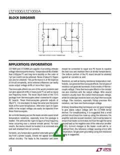
applicaTions inForMaTion
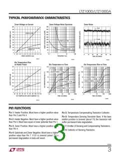
Setting Control Temperature
is because normal operating power dissipation in the
LTZ1000A causes a temperature rise of about 10°C. Of
course both types of devices should be insulated from
ambient. Several minutes of warm-up is usual.
The emitter-base voltage of the control transistor sets the
stabilization temperature for the LTZ1000. With the values
given in the applications, temperature is normally 60°C.
This provides 15°C of margin above a maximum ambient
of45°C,forexample.Productionvariationsinemitter-base
voltage will typically cause about 10°C variation. Since
the emitter-base voltage changes about 2mV/°C and is
very predictable, other temperatures are easily set.
For applications not requiring the extreme precision or
the low noise of the LTZ1000, Linear Technology makes a
broad line of voltage references. Devices like the LT1021
can provide drifts as low as 2ppm/°C and devices such as
the LM399A can provide drifts of 1ppm/°C. Only applica-
tions requiring the very low noise or low drift with time of
theLTZ1000shouldusethisdevice. SeeApplicationNotes
AN-82andAN-86forfurtherinformation.ConsulttheLinear
Technology Applications department for additional help.
Becausehighertemperaturesaccelerateaginganddecrease
long-termstability,thelowesttemperatureconsistentwith
the operating environment should be used. The LTZ1000A
should be set about 10°C higher than the LTZ1000. This
Typical applicaTions
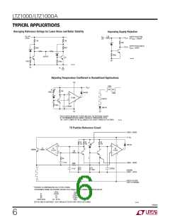
Negative Voltage Reference
ZENER + SENSE
+
V
15V
GND
R4
0.1µF
R2
70k
R3
70k
13k
1
2
5
6
8
5
+
3
4
1k
7
2N3904
LT1013
1N4148
10k
1M
–
7
8
2
–
+
1
LT1013
4
0.1µF
3
400k*
1N4148
R1
120
R5
1k
0.022µF
ZENER – FORCE
ZENER – SENSE
*PROVIDES TEMPERATURE COMPENSATION, DELETE FOR LTZ1000A
APPROXIMATE CHANGE IN REFERENCE VOLTAGE FOR A 100ppm CHANGE IN RESISTOR VALUES:
V– ≥ 10V
100ppm = ∆R(Ω)
0.012Ω
∆V
Z
1ppm
0.3ppm
0.2ppm
1ppm
R1
R2
7Ω
7Ω
∆R = 0.01%
R3
R4/R5 RATIO
1000 TA02
BOTH A1 AND A2 CONTRIBUTE LESS THAN 2µV OF OUTPUT DRIFT OVER A 50°C RANGE
1000afd
5

 Linear [ Linear ]