LTZ1000/LTZ1000A
absoluTe MaxiMuM raTings
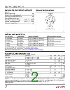
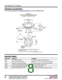
pin conFiguraTion
(Note 1)
BOTTOM VIEW
8
Heater to Substrate...................................................35V
Collector Emitter Breakdown Q1...............................15V
Collector Emitter Breakdown Q2...............................35V
Emitter Base Reverse Bias..........................................2V
7
1
Q2
6
2
Operating Temperature Range .........–55°C ≤ T ≤ 125°C
A
Q1
5
Storage Temperature Range ............–65°C ≤ T ≤ 150°C
A
7V
3
Substrate Forward Bias............................................ 0.1V
4
H8 PACKAGE
TO-5 METAL CAN
T
JMAX
= 150°C,
LTZ1000CH: θ = 80°C/W
JA
LTZ1000ACH: θ = 400°C/W
JA
orDer inForMaTion
LEAD FREE FINISH
LTZ1000ACH#PBF
LTZ1000CH#PBF
LEAD BASED FINISH
LTZ1000ACH
PART MARKING
LTZ1000ACH
LTZ1000CH
PACKAGE DESCRIPTION
SPECIFIED TEMPERATURE RANGE
–55°C to 125°C
8-Lead TO-5 Metal Can (.200 Inch PCD)
8-Lead TO-5 Metal Can (.200 Inch PCD)
PACKAGE DESCRIPTION
–55°C to 125°C
PART MARKING
LTZ1000ACH
LTZ1000CH
SPECIFIED TEMPERATURE RANGE
–55°C to 125°C
8-Lead TO-5 Metal Can (.200 Inch PCD)
8-Lead TO-5 Metal Can (.200 Inch PCD)
LTZ1000CH
–55°C to 125°C
Consult LTC Marketing for parts specified with wider operating temperature ranges.
For more information on lead free part marking, go to: http://www.linear.com/leadfree/
This product is only offered in trays. For more information go to: http://www.linear.com/packaging/
elecTrical characTerisTics (Note 2)
PARAMETER
CONDITIONS
MIN
TYP
MAX
UNITS
Zener Voltage
l = 5mA, (V + VBE ) I = 100µA
7.0
6.9
7.2
7.15
7.5
7.45
V
V
Z
Z
Q1 Q1
l = 1mA, (V + VBE ) I = 100µA
Z
Z
Q1 Q1
Zener Change with Current
Zener Leakage Current
Zener Noise
1mA ≤ I < 5mA
80
20
240
200
2
mV
µA
Z
V = 5V
Z
l = 5mA, 0.1Hz < f < 10Hz
1.2
µV
P-P
Z
Q1
1
= 100µA
Heater Resistance
I ≤ 100µA
200
35
15
35
80
300
420
Ω
V
V
V
L
Heater Breakdown Voltage
Transistor Q1 Breakdown
Transistor Q2 Breakdown
Q1, Q2 Current Gain
I = 10µA, LVCEO
C
20
50
I = 10µA, LVCEO
C
I = 100µA
C
200
450
Thermal Resistance
LTZ1000
LTZ1000A
Time = 5 Minutes
Time = 5 Minutes
80
400
°C/W
°C/W
Long-Term Stability
T = 65°C
2
µV√kHr
Note 1: Stresses beyond those listed under Absolute Maximum Ratings
may cause permanent damage to the device. Exposure to any Absolute
Maximum Rating condition for extended periods may affect device
reliability and lifetime.
Note 2: All testing is done at 25°C. Pulse testing is used for LTZ1000A to
minimize temperature rise during testing. LTZ1000 and LTZ1000A devices
are QA tested at –55°C and 125°C.
1000afd
2

 Linear [ Linear ]