LTC3780
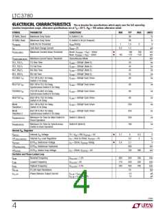
ELECTRICAL CHARACTERISTICS The l denotes the specifications which apply over the full operating
junction temperature range, otherwise specifications are at TA = 25°C. VIN = 15V unless otherwise noted.
SYMBOL
PARAMETER
CONDITIONS
MIN
TYP
MAX
UNITS
PGOOD Output
PGOOD Upper Threshold
PGOOD Lower Threshold
PGOOD Hysteresis
V
V
V
Rising
5.5
7.5
–7.5
2.5
10
%
%
%
V
∆V
OSENSE
OSENSE
OSENSE
FBH
Falling
–5.5
–10
∆V
FBL
Returning
∆V
FB(HYST)
V
PGOOD Low Voltage
I
= 2mA
= 5V
0.1
0.3
1
PGL
PGOOD
I
PGOOD Leakage Current
V
μA
PGOOD
PGOOD
Note 1: Stresses beyond those listed under Absolute Maximum Ratings
may cause permanent damage to the device. Exposure to any Absolute
Maximum Rating condition for extended periods may affect device
reliability and lifetime.
Note 6: The minimum on-time condition is specified for an inductor
peak-to-peak ripple current ≥ 40% of I (see minimum on-time
considerations in the Applications Information section).
Note 7: The LTC3780E is guaranteed to meet performance specifications
from 0°C to 85°C. Performance over the –40°C to 85°C operating junction
temperature range is assured by design, characterization and correlation
with statistical process controls. The LTC3780I is guaranteed over the
–40°C to 125°C operating junction temperature range. The LTC3780MP
is guaranteed and tested over the full –55 to 125°C operating junction
temperature range.
MAX
Note 2: T for the QFN package is calculated from the temperature T and
J
A
power dissipation P according to the following formula:
D
T = T + (P • 34°C/W)
J
A
D
Note 3: The IC is tested in a feedback loop that servos V to a specified
ITH
voltage and measures the resultant V
.
OSENSE
Note 4: Dynamic supply current is higher due to the gate charge being
delivered at the switching frequency.
Note 5: Rise and fall times are measured using 10% and 90% levels. Delay
Note 8: This parameter is guaranteed by design.
Note 9: f
is the running frequency for the application.
OSC
times are measured using 50% levels.
3780fe
5

 Linear Systems [ Linear Systems ]