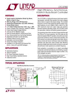
LTC3780
ORDER INFORMATION
LEAD FREE FINISH
LTC3780EG#PBF
LTC3780IG#PBF
LTC3780EUH#PBF
LTC3780IUH#PBF
LEAD BASED FINISH
LTC3780EG
TAPE AND REEL
LTC3780EG#TRPBF
LTC3780IG#TRPBF
LTC3780EUH#TRPBF
LTC3780IUH#TRPBF
TAPE AND REEL
LTC3780EG#TR
PART MARKING
LTC3780EG
LTC3780IG
3780
PACKAGE DESCRIPTION
TEMPERATURE RANGE
–40°C to 85°C
24-Lead Plastic SSOP
24-Lead Plastic SSOP
–40°C to 125°C
–40°C to 85°C
32-Lead (5mm × 5mm) Plastic QFN
32-Lead (5mm × 5mm) Plastic QFN
PACKAGE DESCRIPTION
3780I
–40°C to 125°C
TEMPERATURE RANGE
–40°C to 85°C
PART MARKING
LTC3780EG
LTC3780IG
LTC3780MPG
3780
24-Lead Plastic SSOP
LTC3780IG
LTC3780IG#TR
24-Lead Plastic SSOP
–40°C to 125°C
–55°C to 125°C
–40°C to 85°C
LTC3780MPG
LTC3780MPG#TR
LTC3780EUH#TR
LTC3780IUH#TR
24-Lead Plastic SSOP
LTC3780EUH
32-Lead (5mm × 5mm) Plastic QFN
32-Lead (5mm × 5mm) Plastic QFN
LTC3780IUH
3780I
–40°C to 125°C
Consult LTC Marketing for parts specified with wider operating temperature ranges.
For more information on lead free part marking, go to: http://www.linear.com/leadfree/
For more information on tape and reel specifications, go to: http://www.linear.com/tapeandreel/
ELECTRICAL CHARACTERISTICS The l denotes the specifications which apply over the full operating
junction temperature range, otherwise specifications are at TA = 25°C. VIN = 15V unless otherwise noted.
SYMBOL
PARAMETER
CONDITIONS
MIN
TYP
MAX
UNITS
Main Control Loop
l
l
V
Feedback Reference Voltage
I
= 1.2V, –40°C ≤ T ≤ 85°C (Note 3)
0.792
0.792
0.800
0.800
0.808
0.811
V
V
OSENSE
TH
–55°C ≤ T ≤ 125°C
I
Feedback Pin Input Current
(Note 3)
–5
–50
nA
VOSENSE
V
Output Voltage Load Regulation
(Note 3)
LOADREG
l
l
∆I = 1.2V to 0.7V
0.1
–0.1
0.5
–0.5
%
%
TH
∆I = 1.2V to 1.8V
TH
V
Reference Voltage Line Regulation
Error Amplifier Transconductance
Error Amplifier GBW
V
= 4V to 30V, I = 1.2V (Note 3)
0.002
0.32
0.6
0.02
%/V
mS
REF(LINEREG)
m(EA)
IN
TH
g
g
I
TH
= 1.2V, Sink/Source = 3μA (Note 3)
(Note 8)
(Note 4)
MHz
m(GBW)
I
Input DC Supply Current
Normal
Q
2400
1500
55
μA
μA
μA
Standby
V
V
= 0V, V
= 0V, V
> 2V
= Open
RUN
RUN
STBYMD
STBYMD
Shutdown Supply Current
70
V
Forced Continuous Threshold
Forced Continuous Pin Current
0.76
0.800
–0.18
5.3
0.84
–0.1
5.5
V
μA
V
FCB
I
V
= 0.85V
–0.30
FCB
FCB
V
Burst Inhibit (Constant Frequency)
Threshold
Measured at FCB Pin
BINHIBIT
l
UVLO
Undervoltage Reset
V
Falling
3.8
0.86
–380
0.7
4
V
V
IN
V
Feedback Overvoltage Lockout
Sense Pins Total Source Current
Start-Up Threshold
Measured at V
Pin
0.84
0.4
0.88
OVL
OSENSE
+
–
I
V
V
V
= V = 0V
SENSE
μA
V
SENSE
SENSE
V
V
Rising
STBYMD(START)
STBYMD(KA)
STBYMD
STBYMD
Keep-Alive Power-On Threshold
Rising, V
= 0V
1.25
V
RUN
3780fe
3

 Linear Systems [ Linear Systems ]