Data Sheet
QPW050/060 Series Power Modules; DC-DC converters
36-75Vdc Input; 1.2Vdc to 3.3Vdc Output
March 27, 2008
output voltage sense range given in the Feature
Specifications table i.e.:
Feature Descriptions
Overcurrent Protection
[Vo(+) – Vo(-)] – [SENSE(+) – SENSE(-)] ≤ 10% of
Vo,nom
.
To provide protection in a fault output overload
condition, the module is equipped with internal
current-limiting circuitry and can endure current limit
for few seconds. If overcurrent persists for few
seconds, the module will shut down and remain latch-
off. The overcurrent latch is reset by either cycling the
input power or by toggling the on/off pin for one
second. If the output overload condition still exists
when the module restarts, it will shut down again. This
operation will continue indefinitely until the
The voltage between the Vo(+) and Vo(-) terminals
must not exceed the minimum output overvoltage
shut-down value indicated in the Feature
Specifications table. This limit includes any increase
in voltage due to remote-sense compensation and
output voltage set-point adjustment (trim). See Figure
35. If not using the remote-sense feature to regulate
the output at the point of load, then connect
SENSE(+) to Vo(+) and SENSE(-) to Vo(-) at the
module.
overcurrent condition is corrected.
An auto-restart option is also available.
Although the output voltage can be increased by both
the remote sense and by the trim, the maximum
increase for the output voltage is not the sum of both.
The maximum increase is the larger of either the
remote sense or the trim. The amount of power
delivered by the module is defined as the voltage at
the output terminals multiplied by the output current.
When using remote sense and trim: the output
voltage of the module can be increased, which at the
same output current would increase the power output
of the module. Care should be taken to ensure that
the maximum output power of the module remains at
or below the maximum rated power.
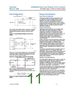
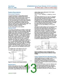
Remote On/Off
Two remote on/off options are available. Positive logic
remote on/off turns the module on during a logic-high
voltage on the ON/OFF pin, and off during a logic low.
Negative logic remote on/off turns the module off
during a logic high and on during a logic low. Negative
logic, device code suffix "1," is the factory-preferred
configuration. To turn the power module on and off,
the user must supply a switch to control the voltage
between the on/off terminal and the VI (-) terminal
(Von/off). The switch can be an open collector or
equivalent (see Figure 34). A logic low is Von/off = 0
V to I.2 V. The maximum Ion/off during a logic low is 1
mA. The switch should maintain a logic-low voltage
while sinking 1 mA. During a logic high, the maximum
Von/off generated by the power module is 15 V. The
maximum allowable leakage current of the switch at
Von/off = 15V is 50 µA. If not using the remote on/off
feature, perform one of the following to turn the unit
on:
For negative logic, short ON/OFF pin to VI(-).
For positive logic: leave ON/OFF pin open.
Figure 35. Effective Circuit Configuration for
Single-Module Remote-Sense Operation Output
Voltage.
Output Voltage Set-Point Adjustment (Trim)
Trimming allows the user to increase or decrease the
output voltage set point of a module. This is
accomplished by connecting an external resistor
between the TRIM pin and either the SENSE(+) or
SENSE(-) pins. The trim resistor should be positioned
close to the module.
Figure 34. Remote On/Off Implementation.
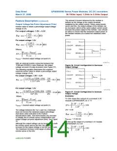
Remote Sense
If not using the trim feature, leave the TRIM pin open.
With an external resistor between the TRIM and
SENSE(-) pins (Radj-down), the output voltage set
point (Vo,adj) decreases (see Figure 36). The
following equation determines the required external-
Remote sense minimizes the effects of distribution
losses by regulating the voltage at the remote-sense
connections. The voltage between the remote-sense
pins and the output terminals must not exceed the
LINEAGE POWER
13

 LINEAGEPOWER [ LINEAGE POWER CORPORATION ]