Data Sheet
QPW050/060 Series Power Modules; DC-DC converters
36-75Vdc Input; 1.2Vdc to 3.3Vdc Output
March 27, 2008
Test Configurations
Design Considerations
Input Source Impedance
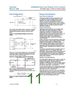
The power module should be connected to a low
ac-impedance source. A highly inductive source
impedance can affect the stability of the power
module. For the test configuration in Figure 31, a
100μF electrolytic capacitor (ESR<0.7Ω at 100kHz),
mounted close to the power module helps ensure the
stability of the unit. Consult the factory for further
application guidelines.
Output Capacitance
High output current transient rate of change (high
Note: Measure input reflected-ripple current with a simulated
source inductance (LTEST) of 12 µH. Capacitor CS offsets
possible battery impedance. Measure current as shown
above.
di/dt) loads may require high values of output
capacitance to supply the instantaneous energy
requirement to the load. To minimize the output
voltage transient drop during this transient, low E.S.R.
(equivalent series resistance) capacitors may be
required, since a high E.S.R. will produce a
correspondingly higher voltage drop during the
current transient.
Figure 31. Input Reflected Ripple Current Test
Setup.
Output capacitance and load impedance interact with
the power module’s output voltage regulation control
system and may produce an ’unstable’ output
condition for the required values of capacitance and
E.S.R.. Minimum and maximum values of output
capacitance and of the capacitor’s associated E.S.R.
may be dictated, depending on the module’s control
system.
The process of determining the acceptable values of
capacitance and E.S.R. is complex and is load-
dependant. Lineage Power provides Web-based tools
to assist the power module end-user in appraising
and adjusting the effect of various load conditions and
output capacitances on specific power modules for
various load conditions.
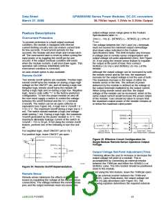
Note: Use a 1.0 µF ceramic capacitor and a 10 µF aluminum
or tantalum capacitor. Scope measurement should be made
using a BNC socket. Position the load between 51 mm and
76 mm (2 in. and 3 in.) from the module.
Figure 32. Output Ripple and Noise Test Setup.
CONTACT AND
DISTRIBUTION LOSSES
Safety Considerations
For safety-agency approval of the system in which the
power module is used, the power module must be
installed in compliance with the spacing and
separation requirements of the end-use safety agency
standard, i.e., UL 60950-1-3, CSA C22.2 No. 60950-
00, and VDE 0805:2001-12 (IEC60950-1).
VO1
VI(+)
IO
II
LOAD
SUPPLY
V
I
(–)
VO2
CONTACT
RESISTANCE
For the converter output to be considered meeting the
requirements of safety extra-low voltage (SELV), the
input must meet SELV requirements.
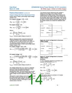
Note: All measurements are taken at the module terminals.
When socketing, place Kelvin connections at module
terminals to avoid measurement errors due to socket contact
resistance.
If the input source is non-SELV (ELV or a hazardous
voltage greater than 60 Vdc and less than or equal to
75Vdc), for the module’s output to be considered as
meeting the requirements for safety extra-low voltage
(SELV), all of the following must be true:
Figure 33. Output Voltage and Efficiency Test
Setup.
LINEAGE POWER
11

 LINEAGEPOWER [ LINEAGE POWER CORPORATION ]