Data Sheet
EHW015A0A Series Eighth-Brick Power Modules
36–75Vdc Input; 5.0Vdc Output; 15A Output Current
June 29, 2009
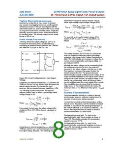
determines the required external resistor value to
obtain a percentage output voltage change of Δ%:
Feature Descriptions (continued)
restarted by cycling the dc input power for at least
one second or by toggling the remote on/off signal for
at least one second. If the unit is configured with the
auto-restart option (4), it will remain in the hiccup mode
as long as the overcurrent condition exists; it operates
normally, once the output current is brought back into
its specified range. The average output current during
5.11×V
× (100 + Δ%)
⎡
⎤
511
o,set
Rtrim −up
=
−
−10.22 ΚΩ
⎢
⎣
⎥
1.225 × Δ%
Δ%
⎦
⎛
⎜
⎜
⎝
⎞
⎟
⎟
⎠
Vdesired − Vo,set
Where
Δ% =
× 100
Vo,set
hiccup is 10% IO, max
.
For example, to trim-up the output voltage of the
module by 5% to 5.25V, Rtrim-up is calculated is as
follows:
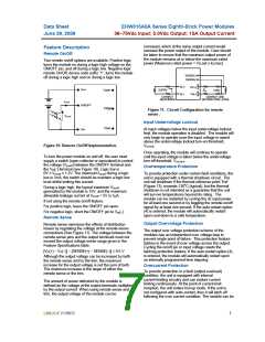
Output Voltage Programming
Trimming allows the output voltage set point to be
increased or decreased, this is accomplished by
connecting an external resistor between the TRIM pin
and either the VO(+) pin or the VO(-) pin.
Δ % = 5
5.11 × 5.0 × (100 + 5) 511
⎡
⎤
Rtrim −up
=
−
− 10.22 ΚΩ
⎢
⎣
⎥
⎦
1.225 × 5
5
Rtrim−up = 325.6ΚΩ
The voltage between the VO(+) and VO(–) terminals
must not exceed the minimum output overvoltage
protection value shown in the Feature Specifications
table. This limit includes any increase in voltage due to
remote-sense compensation and output voltage set-
point adjustment trim.
VIN(+)
VO(+)
VOTRIM
VO(-)
Rtrim-up
ON/OFF
LOAD
Although the output voltage can be increased by both
the remote sense and by the trim, the maximum
increase for the output voltage is not the sum of both.
The maximum increase is the larger of either the
remote sense or the trim. The amount of power
Rtrim-down
VIN(-)
delivered by the module is defined as the voltage at the
output terminals multiplied by the output current. When
using remote sense and trim, the output voltage of the
module can be increased, which at the same output
current would increase the power output of the module.
Care should be taken to ensure that the maximum
output power of the module remains at or below the
maximum rated power (Maximum rated power = VO,set x
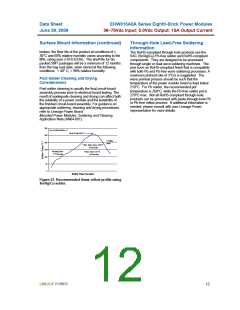
Figure 12. Circuit Configuration to Trim Output
Voltage.
Connecting an external resistor (Rtrim-down) between the
TRIM pin and the VO(-) (or Sense(-)) pin decreases the
output voltage set point. To maintain set point
accuracy, the trim resistor tolerance should be ±1.0%.
IO,max).
The following equation determines the required
external resistor value to obtain a percentage output
voltage change of Δ%
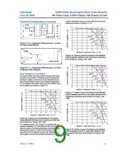
Thermal Considerations
The power modules operate in a variety of thermal
environments; however, sufficient cooling should be
provided to help ensure reliable operation.
511
⎡
⎤
Rtrim − down
=
− 10 .22 ΚΩ
⎢
⎣
⎥
⎦
Δ%
Considerations include ambient temperature, airflow,
module power dissipation, and the need for increased
reliability. A reduction in the operating temperature of
the module will result in an increase in reliability. The
thermal data presented here is based on physical
measurements taken in a wind tunnel.
⎛
⎜
⎜
⎝
⎞
Vo,set − Vdesired
Where
⎟
⎟
⎠
Δ% =
×100
Vo,set
For example, to trim-down the output voltage of the
module by 8% to 4.6V, Rtrim-down is calculated as
follows:
Δ% = 8
The thermal reference point, Tref used in the
specifications for open frame modules is shown in
Figure 13. For reliable operation this temperature
should not exceed 117oC.
511
8
⎡
⎤
Rtrim−down
=
−10.22 ΚΩ
⎢
⎣
⎥
⎦
The thermal reference point, Tref used in the
specifications for modules with heatplate is shown in
Figure 14. For reliable operation this temperature
should not exceed 105oC.
Rtrim −down = 53 .6ΚΩ
Connecting an external resistor (Rtrim-up) between the
TRIM pin and the VO(+) (or Sense (+)) pin increases
the output voltage set point. The following equation
LINEAGE POWER
8

 LINEAGEPOWER [ LINEAGE POWER CORPORATION ]