Data Sheet
EHW015A0A Series Eighth-Brick Power Modules
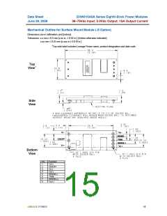
36–75Vdc Input; 5.0Vdc Output; 15A Output Current
June 29, 2009
REFLOW TIME (S)
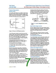
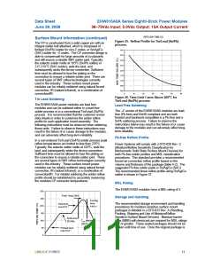
Surface Mount Information (continued)
Figure 25. Reflow Profile for Tin/Lead (Sn/Pb)
process.
The CP is constructed from a solid copper pin with an
integral solder ball attached, which is composed of
tin/lead (Sn/Pb) solder for non-Z codes, or Sn/Ag/Cu
(SAC) solder for –Z codes. The CP connector design is
able to compensate for large amounts of co-planarity
and still ensure a reliable SMT solder joint. Typically,
the eutectic solder melts at 183oC (Sn/Pb solder) or
217-218 oC (SAC solder), wets the land, and
subsequently wicks the device connection. Sufficient
time must be allowed to fuse the plating on the
connection to ensure a reliable solder joint. There are
several types of SMT reflow technologies currently
used in the industry. These surface mount power
modules can be reliably soldered using natural forced
convection, IR (radiant infrared), or a combination of
convection/IR.
240
235
230
225
220
215
210
205
200
0
10
20
30
40
50
60
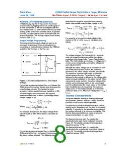
Figure 26. Time Limit Curve Above 205oC for
Tin/Lead (Sn/Pb) process
Tin Lead Soldering
The EHW015A0A power modules are lead free
modules and can be soldered either in a lead-free
solder process or in a conventional Tin/Lead (Sn/Pb)
process. It is recommended that the customer review
data sheets in order to customize the solder reflow
profile for each application board assembly. The
following instructions must be observed when soldering
these units. Failure to observe these instructions may
result in the failure of or cause damage to the modules,
and can adversely affect long-term reliability.
Lead Free Soldering
The –Z version of the EHW015A0A modules are lead-
free (Pb-free) and RoHS compliant and are both
forward and backward compatible in a Pb-free and a
SnPb soldering process. Failure to observe the
instructions below may result in the failure of or cause
damage to the modules and can adversely affect long-
term reliability.
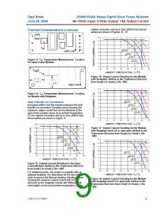
Pb-free Reflow Profile
In a conventional Tin/Lead (Sn/Pb) solder process peak
reflow temperatures are limited to less than 235oC.
Typically, the eutectic solder melts at 183oC, wets the
land, and subsequently wicks the device connection.
Sufficient time must be allowed to fuse the plating on
the connection to ensure a reliable solder joint. There
are several types of SMT reflow technologies currently
used in the industry. These surface mount power
modules can be reliably soldered using natural forced
convection, IR (radiant infrared), or a combination of
convection/IR. For reliable soldering the solder reflow
profile should be established by accurately measuring
the modules CP connector temperatures.
Power Systems will comply with J-STD-020 Rev. C
(Moisture/Reflow Sensitivity Classification for
Nonhermetic Solid State Surface Mount Devices) for
both Pb-free solder profiles and MSL classification
procedures. This standard provides a recommended
forced-air-convection reflow profile based on the
volume and thickness of the package (table 4-2). The
suggested Pb-free solder paste is Sn/Ag/Cu (SAC).
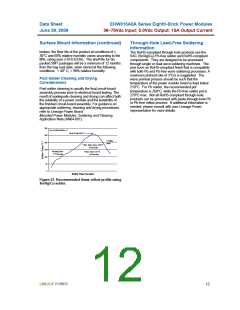
The recommended linear reflow profile using Sn/Ag/Cu
solder is shown in Figure 27.
MSL Rating
The EHW015A0A modules have a MSL rating of 2.
300
Peak Temp 235oC
Storage and Handling
250
Cooling
zone
The recommended storage environment and handling
procedures for moisture-sensitive surface mount
packages is detailed in J-STD-033 Rev. A (Handling,
Packing, Shipping and Use of Moisture/Reflow
Sensitive Surface Mount Devices). Moisture barrier
bags (MBB) with desiccant are required for MSL ratings
of 2 or greater. These sealed packages should not be
broken until time of use. Once the original package is
Heat zone
200
1- 4 oCs-1
max 4oCs-1
150
10 0
50
Soak zone
30-240s
T
lim above
205oC
Preheat zone
max 4oCs-1
0
LINEAGE POWER
11

 LINEAGEPOWER [ LINEAGE POWER CORPORATION ]