KEMET®
APPLICATION NOTES FOR TANTALUM CAPACITORS
Dissipation factor also increases with increasing RH. The
limiting change, at equilibrium with 95% RH, is approxi-
mately 50%.
DC leakage current may rise upon exposure to a
combination of high temperature and high humidity, but is
normally restored by voltage conditioning under standard
conditions. The increase will be greater than that experi-
enced under temperature influence alone because of con-
duction through absorbed water.
Hermetically-sealed and non-hermetic Series may be
affected by absorption of water on external insulating sur-
faces. The water film may also attract a layer of dust from
the air, increasing the effect. The most sensitive parame-
ter is leakage current.
INTRODUCTION
KEMET solid tantalum capacitors are identified by the
initial “T,” followed by a unique “Series” number; for exam-
ple, T110, T322, T350, etc. Each Series denotes a gener-
al physical form and type of encapsulation, as well as lim-
its on dimensions and certain electrical characteristics
under standard conditions of 25°C, 50% relative humidity,
and one atmosphere pressure. Specific requirements are
set forth in the respective Product Series in this catalog. All
Military products are 100% electrically screened for the
parameters shown in the respective product section. For
non-military product, all series are 100% screened for
leakage, capacitance and dissipation factor. All Series are
inspected to electrical limits using a minimum .1% AQL
sampling plans, according to the Military Standard
MIL-STD-105, even after 100% testing. This sampling
plan, to the best of KEMET Electronics’ knowledge, meets
or exceeds the generally accepted industry standard for
similar products. KEMET capacitors may also be supplied,
with prior agreement, to meet specifications with require-
ments differing from those of KEMET catalogs. Reference
ESR values are provided but are NOT 100% screened
These Notes apply generally to all KEMET solid tan-
talum capacitors and illustrate typical performance under
normal application conditions, except where noted.
Certain Series will respond differently to various environ-
mental conditions. For example, hermetically sealed
series are relatively immune to humidity effects, while
plastic-encased series are not. The intent of these Notes
is not to delineate such differences but to provide general-
ized information concerning performance characteristics.
3. POLARITY
These capacitors are inherently polar devices and
may be permanently damaged or destroyed if connected
with the wrong polarity. The positive terminal is identified
on the capacitor body by a polarity mark and the capacitor
body may include an obvious geometrical shape.
However, some Series contain two capacitors connected
(negative-to-negative) to form “non-polar” capacitors.
Rated voltage (see para. 8) may be applied to these
Series in either direction.
4. OPERATING ENVIRONMENT
Most of the discussion under “Storage Conditions”
will apply also when capacitors are operated within the
applicable electrical ratings described below. The tempo-
rary increase in leakage current (at standard conditions)
following elevated-temperature exposure is not observed,
however, if the capacitors are operated with adequate DC
voltage applied.
1. GENERAL APPLICATION CLASS
Solid tantalum capacitors are usually applied in cir-
cuits where the AC component is small compared to the
DC component. Typical uses known to KEMET Electronics
include blocking, by-passing, decoupling, and filtering.
They are also used in timing circuits. If two of these polar
capacitors are connected “back-to-back” (i.e., negative-to-
negative or positive-to-positive), the pair may be used in
AC applications (as a non-polar device).
5. CAPACITANCE
Capacitance is measured at 120 Hz and 25° C with
up to 1 volt rms applied. Note that, in either operation,
peak AC plus DC bias must not exceed either rated volt-
age (normally polarized) or 15% of rated voltage in the
reverse direction at 25°C. Measurement circuits are of
high impedance, however, and under these conditions 1
volt rms may be applied even to 6 volt capacitors (23%
peak reversal) without a DC bias. DC bias is thus normal-
ly not used, except when rated voltage is below 6 volts and
the AC signal level exceeds 0.3 vrms. However,
MIL-C-39003 provides for up to 2.2 volts DC.
DC bias causes a small reduction in capacitance, up
to about 2% when full rated voltage is applied as bias. DF
is also reduced by the presence of DC; rated voltage may
cause a decrease in DF of about 0.2% (e.g., a decrease
from 3.6 to 3.4% DF).
2. STORAGE CONDITIONS
Capacitors may be stored without applied voltage
over the operating temperature range specified in the cat-
alogs for each Series. The range is from -55 to +125° C for
all Series.
Tantalum capacitors do not lose capacitance from the
“de-forming” effect as do liquid-electrolytic capacitors.
Storage at high temperature may cause a small, tempo-
rary increase in leakage current (measured under stan-
dard conditions), but the original value is usually restored
within a few minutes after application of rated voltage.
Series which are not hermetically sealed exhibit
reversible changes in parameters with respect to relative
humidity (RH). Capacitance increases with increasing
humidity. The limiting change, reached upon establish-
ment of equilibrium with the environment, is approximate-
ly -5% to +12% over the range from 25% to 95% RH,
referred to the standard 50% RH. The amount of change
is dependent upon size (capacitance and voltage rating,
ie: CV product); small sizes might change no more than
±5%. Equilibrium at such extremes is seldom attained by
plastic-cased capacitors, and the change in capacitance is
consequently less. The rate of response to humidity
changes increases with increasing temperature.
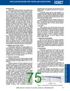
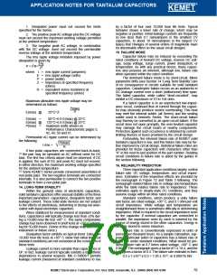
Capacitance changes very little below 1 kHz but
decreases more noticeably at higher frequencies. Larger
capacitance values decline more rapidly than small rat-
ings. The effect of frequency upon capacitance is shown in
Figure 1.
1.0
Reference
1.0 at 120Hz
0.9
100
1K
10K
Frequency - Hertz
Figure 1. Normal Effect of Frequency upon Capacitance
KEMET Electronics Corporation, P.O. Box 5928, Greenville, S.C. 29606 (864) 963-6300
75

 KEMET [ KEMET CORPORATION ]