KEMET®
PACKAGING INFORMATION
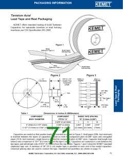
KEMET offers Solid Tantalum Capacitors fully compatible for use with automatic insertion machines for radial-lead components. Aris Reeling meets
allrequirementsofEIAStandardRS-468.KEMETcapacitorsarewoundonaprecisionmadeARISReelPackage.ARISAmmoPackageisalsoavailable.
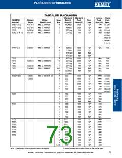
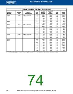
Tantalum Dipped Radial – ARIS Specification (Automatic Radial Insertion System)
Tantalum Dipped Tape and Reel Dimensions in Millimeters & (Inches)
Nominal
mm (inch)
Tolerance
mm (inch)
Nominal
mm (inch)
Tolerance
mm (inch)
Dimension
Symbol
Dimension
Symbol
Body Height (1)
A
17.0 (0.67)
Maximum
Component Pitch (5)
P
12.7 (.500)
± 1.0 (± .039)
± 0.3 (±.012)
± 0.7 (±.028)
Body Width (1)
A
1
10.2 (0.40)
4.0 (.157)
Maximum
Sprocket Hole
Pitch (2)
P
P
12.7 (.500)
0
1
Sprocket Hole
Diameter
Lead Diameter
D
± 0.3 (±.012)
± 0.05 (.002)
Sprocket Hole
Center to Lead
Center (3) (4)
Sprocket Hole Center
to Component (5)
Center
See Note
Below
0
d
0.51 or 0.64
(.020) (.025)
See Note Below
P
See Note
Below
2
0
Lead Center (4)
F
Component Base
to Tape Center (4)
Lead Standoff
H
H
H
C-7301
16.0 (.630) 18.0 (.709)
C-7301
16.0 (.630) 18.0 (.709)
32.25 (1.270)
C-7303
C-7301
±0.5 (±.020) Minimum
C-7301 C-7303
±0.5 (±.020) Minimum
Maximum
C-7303
Body Thickness
T
T
10.2 (.400)
Maximum
C-7303
Total Tape Thickness
Carrier Tape Width
0.7 (0.28)
18.0 (.709)
± .02 (.008)
+ 1.0/-0.5
(+.039/-.020)
+ 1.0/-0.8
0
1
Height
W
Component Height
Above Tape Center
Component Alignment
Front to Rear
Hold-Down Tape
Width
Sprocket Hole
Location
Hold-Down Tape
Location
W
15mm or 6mm
(.561) (.236) (+.039/-.031)
9.0 (.354)
0
1
2
∆ H
0
1.0 (.039)
Maximum
Maximum
W
W
+.075/-0.5
(+.030/-.020)
Maximum
Cut Out Length
L
11.0 (.433)
1.0 (.039)
12mm (.472)
Lead Protrustion
L
1
T
0
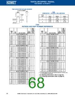
Notes: (1) See page 62 for T35X and page 69 for T39X specific dimensions.
(2) Cumulative pitch error ± 1.0mm (.039) maximum in 20 consecutive sprocket hole locations.
(3) Measured at bottom of standoff.
∆H
A1
P
2
(4) P and F measured at egress from carrier tape.
(5) P and P measured at egress from carrier tape.
2
P
1
A
➀ ➁ ➂
H1
On polar devices, the positive (+) lead exits from container first.
1MM Max.
(.039")
F
* Lead spacings are 2.5mm (.098") center-to-center (T350 A-H)
** Lead spacings are 5.0mm (.197") center-to-center
H
W
2
L
H0
W1
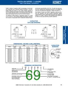
P1 Dimensions:
Lead
F Dimensions:
0.100" ± .015
W
W0
Spacing
Tape
Carrier
T396/8*
T350/1*
0.125" ± .015
➀
➁
➂
0.100"
0.125"
0.200"
0.250"
0.100"
–
–
–
–
–
0.200 ± .028"
0.200" ± .015
W
2
0.187 ± .028"
0.250" ± .015"
0.100 " ± .015 (3 leaded)
0.150 ± .028"
D0
L
1
0.125 ± .028"
0.100 ± .028" ( 3 leaded)
d
T352/3/4/5/6**
P
0
P
1
T
Tantalum Molded Radial – ARIS Specification (Automatic Radial Insertion System)
Tantalum Molded Tape and Reel Dimensions in Millimeters & (Inches)
Nominal
mm (inch)
Tolerance
mm (inch)
Nominal
mm (inch)
Tolerance
mm (inch)
Dimension
Symbol
Dimension
Symbol
Body Height (1)
A
10.50 (.413)
15.24 (.600)
4.0 (.157)
± .38 (±.015)
Maximum
Maximum ± .38
± (.015)
Component Pitch (5)
P
12.7 (.500)
± 1.0 (± .039)
± 0.3 (±.012)
± 0.7 (±.028)
Body Width (1)
A
1
Sprocket Hole
Pitch (3)
Sprocket Hole
Center to Lead
Center (4) (5)
Sprocket Hole Center
to Component Center
Body Thickness
P
P
12.7 (.500)
0
1
Sprocket Hole
Diameter
Lead Diameter
D
± 0.3 (± .012)
3.85 4.76 5.1
(.152) (.188) (.201)
0
d
0.51 or 0.64
(.020) (.025)
± 0.05 or ± .03
(± .001)
+ 0.8/ - 0.2
(+ .032/ -.008)
Reference Only
P
6.35 (.250)
6.35 (.250)
0.7 (0.28)
18.0 (.709)
± 1.3 (±.051)
± 1.3 Maximum
± .02 (±.008)
2
Lead Center (5)
F
5.0
2.5
(.197) (.098)
18.0 (.709)
T
T
0
Component Base
to Tape Center (2)(4)(6)
Lead Standoff
H
H
H
Total Tape Thickness
Carrier Tape Width
N/A
0
1
Height
+ 1.0/-0.5
(+.039/-.020)
+ 1.0/-0.8
(+.039/.031)
+.075/-0.5
(+.030/-.020)
Maximum
W
W
Component Height
Above Tape Center
Component Alignment
Front to Rear
32.25 (1.270)
0
Maximum
Hold-Down Tape
Width
Sprocket Hole
Location
Hold-Down Tape
Location
15 or
6
0
1
2
∆ H
± 2.0
(± .079)
Maximum
(.561) (.236)
9.0 (.354)
W
W
Cut Out Length
L
11.0 (.433)
2.0 (.079)
3.0 or 12.0
(.118) (.472)
Lead Protrustion
L
1
Maximum
Notes: (1) See page 50 for T330, page 53 for T340 and page 59 for T35X specific dimensions.
(2) Reference Only
A
1
P
2
(3) Cumulative pitch error ± 1.0mm (.039") maximum in 20 consecutive sprocket hole locations.
(4) Measured at bottom of standoff.
➀
➁
➂
A
(5) P, P1 and F measured at egress from carrier tape.
(6) H dimensions for T370 D and E 16.5mm ± 0.5mm (0.650" ± 0.020")
P
H1
F
On polar devices, the positive (+) lead exits from container first.
* Lead spacings are 2.5mm (.098") center-to center
** Lead spacings are 5.0mm (.197") center-to-center.
H
W
2
W1
W
0
W
T370
➀
➁
➂
W2
T340**
T330**
D0
L
0
1
P
P1
T
d
72
KEMET Electronics Corporation, P.O. Box 5928, Greenville, S.C. 29606 (864) 963-6300

 KEMET [ KEMET CORPORATION ]