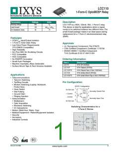
LCC110
INTEGRATED
CIRCUITS
DIVISION
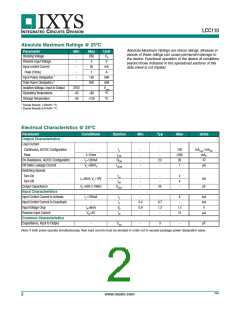
Absolute Maximum Ratings @ 25ºC
Absolute Maximum Ratings are stress ratings. Stresses in
excess of these ratings can cause permanent damage to
the device. Functional operation of the device at conditions
beyond those indicated in the operational sections of this
data sheet is not implied.
Parameter
Blocking Voltage
Min
-
Max
350
5
Unit
VP
Reverse Input Voltage
Input control Current
Peak (10ms)
-
V
-
-
50
mA
A
1
Input Power Dissipation 1
Total Power Dissipation 2
Isolation Voltage, Input to Output
Operating Temperature
Storage Temperature
-
150
800
-
mW
mW
Vrms
ºC
-
3750
-40
-40
+85
+125
ºC
1 Derate linearly 1.33mW / ºC.
2 Derate linearly 6.67mW / ºC.
Electrical Characteristics @ 25ºC
Parameter
Conditions
Symbol
Min
Typ
Max
Units
Output Characteristics
Load Current
Continuous, AC/DC Configuration
Peak
-
IL
-
-
-
-
-
-
120
350
35
mArms / mADC
t=10ms
IL=120mA
VL=350VP
ILPK
RON
ILEAK
mAP
On-Resistance, AC/DC Configuration
Off-State Leakage Current
Switching Speeds
23
-
1
µA
Turn-On
ton
toff
-
-
-
-
-
4
4
-
IF=8mA, VL=10V
VL=50V, f=1MHz
ms
pF
Turn-Off
Output Capacitance
COUT
25
Input Characteristics
Input Control Current to Activate
Input Control Current to Deactivate
Input Voltage Drop
IL=120mA
-
IF
IF
-
-
8
-
mA
mA
V
0.4
0.9
-
0.7
1.2
-
IF=8mA
VR=5V
VF
IR
1.4
10
Reverse Input Current
Common Characteristics
Capacitance, Input to Output
A
-
CI/O
-
3
-
pF
Note: If both poles operate simultaneously, then load current must be derated in order not to exceed package power dissipation value.
R06
2
www.ixysic.com

 IXYS [ IXYS CORPORATION ]