DSA 90 C 200 HB
preliminary
100
10
1
1000
100
10
10.000
1.000
0.100
0.010
0.001
TVJ = 150°C
125°C
100°C
75°C
TVJ= 25°C
TVJ
=
150°C
125°C
25°C
50°C
25°C
0.2 0.4 0.6 0.8 1.0 1.2 1.4
0
50
100
150
200
0
40
80
120 160 200
VF [V]
VR [V]
VR [V]
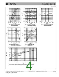
Fig. 1 Maximum forward voltage
drop characteristics
Fig. 2 Typ. reverse current IR
versus reverse voltage VR
Fig. 3 Typ. junction capacitance CT
versus reverse voltage VR
100
90
80
70
60
50
40
30
20
10
0
100
90
80
70
60
50
40
30
20
10
0
DC
d = 0.5
d =
DC
0.5
0.33
0.25
0.17
0.08
0
10 20 30 40 50 60 70 80 90
0
40
80
TC [°C]
120
160
IF(AV) [A]
Fig. 4 Avg: forward current IF(AV)
versus case temperature TC
Fig. 5 Forward power loss
characteristics
1
D = 0.5
0.33
0.25
Single Pulse
0.17
0.08
0.1
DSA90C200HB
0.001
0.01
0.1
1
t [s]
Fig. 6 Transient thermal impedance junction to case atvarious duty cycles
IXYS reserves the right to change limits, conditions and dimensions.
20080605b
Data according to IEC 60747and per diode unless otherwise specified
© 2008 IXYS all rights reserved

 IXYS [ IXYS CORPORATION ]