Flex Circuit Cable Assembly
Terminating to Flexible Circuits
For a low profile finish, it is best to terminate flexible circuits in line with the contacts. Since most Microminiature
Connectors have contacts set into two or three rows, termination is generally an easy process.
• The diagrams below provide guidance for pad arrangements to suit MDM Microminiature
Connectors, ensuring the circuits are inserted into the potting correctly and accurately.
• The length of the pad is optional but it is important to provide enough cover-lay, especially at
the edges of the circuit, to avoid delamination. We suggest at least 0,51 mm (.020 inches).
Our standard potting shrouds provide support to the circuit with a dimension of 7,00 mm
(.275 inches) from the rear of the flange.
Please consult Customer Service for specific flex circuit assembly design considerations and requirements.
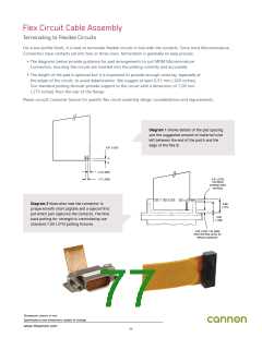
Diagram 1 shows details of the pad spacing
and the suggested amount of material to be
left between the end of the pad A and the
edge of the flex B.
0,51 (.020)
A
B
2,16 (.085)
0,51 (.020)
COVERLAY
1.27 (.050)
EXTENDS INTO
POTTING
Diagram 2 illustrates how the connector is
6,99
(.275)
prepared with short pigtails and a special first
pot which just captures the contacts. The final
back potting for strength is controlled by our
standard 7,00 (.275) potting fixtures.
4,98
(.196)
2,00 (.079) 1,53 (060)
FIRST POTTING LEVEL TO
RETAIN CONTACTS
Dimensions shown in mm
Specifications and dimensions subject to change
www.ittcannon.com
77

 ITT [ ITT Cannon ]